Solar energy heat collector

A solar heat collecting and heat conducting tube technology, applied in solar thermal devices, solar thermal collectors, solar thermal energy and other directions, can solve the problems of reduced heat collection efficiency, limited surface area, low energy absorption rate, etc., to improve utilization and improve absorption The effect of high utilization rate, conversion rate, and energy absorption rate

Inactive Publication Date: 2009-03-04
ZHUHAI HUISHENG ENERGY SOURCE TECH DEV
View PDF0 Cites 6 Cited by
  • Summary
  • Abstract
  • Description
  • Claims
  • Application Information

AI Technical Summary

Problems solved by technology

Existing solar heat collecting tubes are all made of glass, and a coating with solar selective absorption is provided on the glass tube wall. In order to reduce heat loss, some also use vacuum tube structure, but the existing heat collecting tubes can only The surface of sunlight absorbs heat, its surface area is inherently limited and cannot be fully used to absorb solar energy, so its energy absorption rate is low, and solar energy cannot be fully and effectively used
Moreover, the existing glass heat collecting tubes are easily damaged, especially in cold areas in winter, not only the water temperature cannot meet the requirements, but also it is easy to freeze and burst
In addition, the coating of the existing solar collector tubes for solar selective absorption is prone to failure, which greatly reduces the heat collection efficiency and shortens the service life.

Method used


Image

  • Solar energy heat collector

Examples


Embodiment Construction

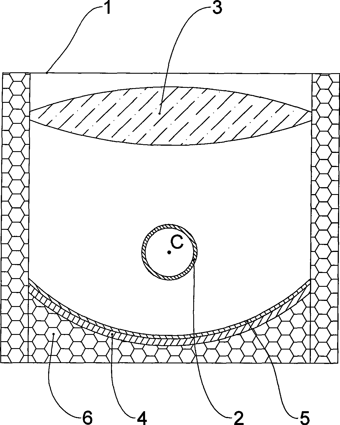
[0017] Such as figure 1 As shown, the present invention includes a casing 1, a heat pipe 2, a focusing convex lens 3, and a focusing concave reflector 4. The heat pipe 2, the focusing convex lens 3, and the focusing concave reflector 4 are all arranged on the In the housing 1, the focusing convex lens 3 and the focusing concave reflector 4 are elongated and arranged in parallel with the heat pipe 2 in the length direction. The focusing convex lens 3 and the focusing concave reflector The focal points of 4 are all in a linear shape, and the lines connecting the focal points coincide with the axis C of the heat pipe 2. The heat pipe 2 is equipped with a heat conduction medium, the heat conduction medium is water, and the outer periphery of the housing 1 is covered There is an insulating material layer 6, the insulating material layer 6 can prevent the solar energy entering the housing 1 and the heat absorbed by the heat pipe 2 from dissipating, further improving the utilization ...


PUM


Abstract

The invention discloses a solar energy collector device which has high energy absorption rate and is capable of effectively utilizing solar energy. The invention comprises an outer housing (1), a heat pipe (2), a focusing convex lens (3) and a focusing concave reflector (4), wherein, the heat pipe (2), the focusing convex lens (3) and the focusing concave reflector (4) are all arranged in the outer housing (1); the focusing convex lens (3) and the focusing concave reflector (4) are both stripe-shaped, and are arranged in parallel to the heat pipe (2) in the lengthwise direction; the focuses of the focusing convex lens (3) and the focusing concave reflector (4) are linear, and the focus links superpose with the axis (C) of the heat pipe (2); and heat-conducting medium is arranged in the heat pipe (2). The invention can be widely used to the technical field of solar energy utilization.

Description

technical field [0001] The invention relates to a solar heat collecting device. Background technique [0002] Solar energy has the outstanding characteristics of green, environmental protection, pollution-free, and energy-saving. It is an inexhaustible source of energy, but its application is limited due to its low energy absorption and conversion efficiency. Utilizing solar energy to produce hot water has been widely used, and the solar heat collecting device generally used at present is mainly a solar heat collecting tube. Existing solar heat collecting tubes are all made of glass, and a coating with solar selective absorption is provided on the glass tube wall. In order to reduce heat loss, some also use vacuum tube structure, but the existing heat collecting tubes can only The heat is absorbed on the surface of the sunlight, and its surface area is inherently limited and cannot be fully used to absorb solar energy, so its energy absorption rate is low, and the solar ene...

Claims


Application Information

Patent Timeline
Patent Type & Authority Applications(China)
IPC IPC(8): F24J2/08F24J2/10F24J2/24F24J2/46F24J2/48G02B1/10F24S10/70F24S23/30F24S23/70
CPCY02E10/40F24J2/08F24J2/10F24S23/30F24S23/70
Inventor 聂民杨奇飞
Owner ZHUHAI HUISHENG ENERGY SOURCE TECH DEV
Why Eureka
Try Eureka