Image forming method and image forming apparatus
An image and equipment technology, applied in the field of image formation and image formation equipment, can solve the problems of difficulty in controlling the amount of ink discharge, difficulty in obtaining stable images, etc.
- Summary
- Abstract
- Description
- Claims
- Application Information
AI Technical Summary
Problems solved by technology
Method used
Image
Examples
no. 1 example
[0039] Referring to FIG. 1, an example of an image forming apparatus according to the present invention will be described.
[0040] FIG. 1 is a perspective view showing a schematic diagram of a line matrix printer as an example of an image forming apparatus according to the present invention.
[0041] A line printer (hereinafter referred to as "printer") 10 includes printing heads K1, K2, K3, and K4 that discharge ink into a plurality of labels 14 (constituting an example of printing media) on each label to form an image. The label 14 is temporarily adhered to the surface of the rolled board 12 . While forming an image, the print heads K1, K2, K3 and K4 remain stationary and never move. Black ink droplets are discharged from the respective print heads K1 to K4. Together with the plate 12 , the label 14 is conveyed at a constant speed in the direction of arrow A by conveying rollers 18 and 20 driven by a conveying motor 16 .
[0042] Ink discharge port arrays are formed in ...
no. 2 example
[0061] refer to Figure 4 , another example of the image forming method using the printer 10 having the aforementioned configuration will be described. Figure 4 is a flowchart showing a second embodiment of the image forming method according to the present invention. In this regard, as Figure 9A and 9B As shown, the basic assignment is that rasters 1, 2, 3 and 4 are associated with print heads K1, K2, K3 and K4, respectively.
[0062] Figure 4 The shown flow is a flow of an image forming method of the type that detects the number of dots to be ejected from the respective print heads K1 to K4 before forming an image on a printing medium (label 14 in this example), and based on the detected The basic allocation is changed by the number of dots to be ejected from the respective print heads K1 to K4. Specifically, the raster allocation is arbitrarily changed for each page. Assign the coldest printhead to the raster that needs to eject the greatest number of dots onto the p...
no. 3 example
[0068] refer to Figure 6 , a third embodiment of the present invention will be described.
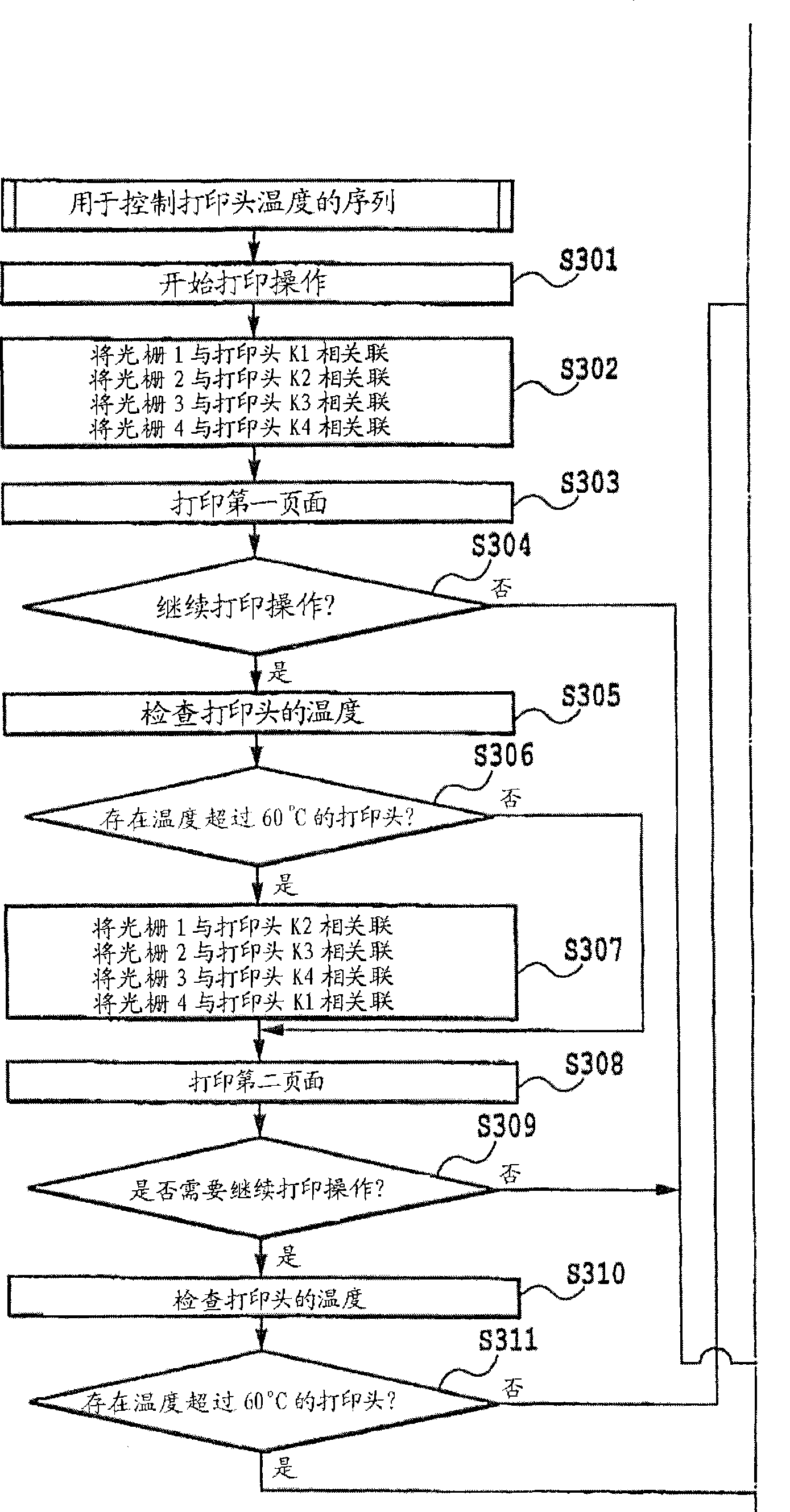
[0069] Figure 6 is a flowchart showing a third embodiment of the image forming method according to the present invention. Apart from Figure 6The flow shown involves modifying the Figure 3A and 3B In addition to the steps obtained from the portion of the flowchart shown, Figure 6 The process shown and Figure 3A and 3B The flow shown is the same. exist Figure 6 Marked with a dotted line in the modified Figure 3A and 3B The steps obtained from the portion of the flowchart shown. Due to the process before and after the steps obtained by modifying the same Figure 3A and 3B The procedure shown is the same as in Figure 6 This part of the process is omitted. Steps S601 and S602 are added to Figure 3A and 3B The procedure shown in this constitutes Figure 6 process shown in .
[0070] In the first embodiment, only whether the highest temperature among the temperatur...
PUM
 Abstract
Description
Claims
Application Information
 - R&D
- Intellectual Property
- Life Sciences
- Materials
- Tech Scout
- Unparalleled Data Quality
- Higher Quality Content
- 60% Fewer Hallucinations
Browse by: Latest US Patents, China's latest patents, Technical Efficacy Thesaurus, Application Domain, Technology Topic, Popular Technical Reports.
© 2025 PatSnap. All rights reserved.Legal|Privacy policy|Modern Slavery Act Transparency Statement|Sitemap|About US| Contact US: help@patsnap.com


