
Head driving device and head driving method for ink jet printer, and ink jet printer

A technology of inkjet printers and drive devices, which is applied in printing and other fields, and can solve problems such as excessive heat dissipation plates and inability to drive pulse output circuits.

Inactive Publication Date: 2009-02-25
SEIKO EPSON CORP
View PDF2 Cites 4 Cited by
  • Summary
  • Abstract
  • Description
  • Claims
  • Application Information

AI Technical Summary

Problems solved by technology

However, in conventional inkjet printers that use push-pull transistors to amplify the current of actuator drive pulses, the heat sink for cooling the transistors is too large. ink head problem

Method used


Image

  • Head driving device and head driving method for ink jet printer, and ink jet printer
  • Head driving device and head driving method for ink jet printer, and ink jet printer
  • Head driving device and head driving method for ink jet printer, and ink jet printer

Examples


Embodiment Construction

[0027] Next, a first embodiment of the inkjet printer of the present invention will be described with reference to the drawings.

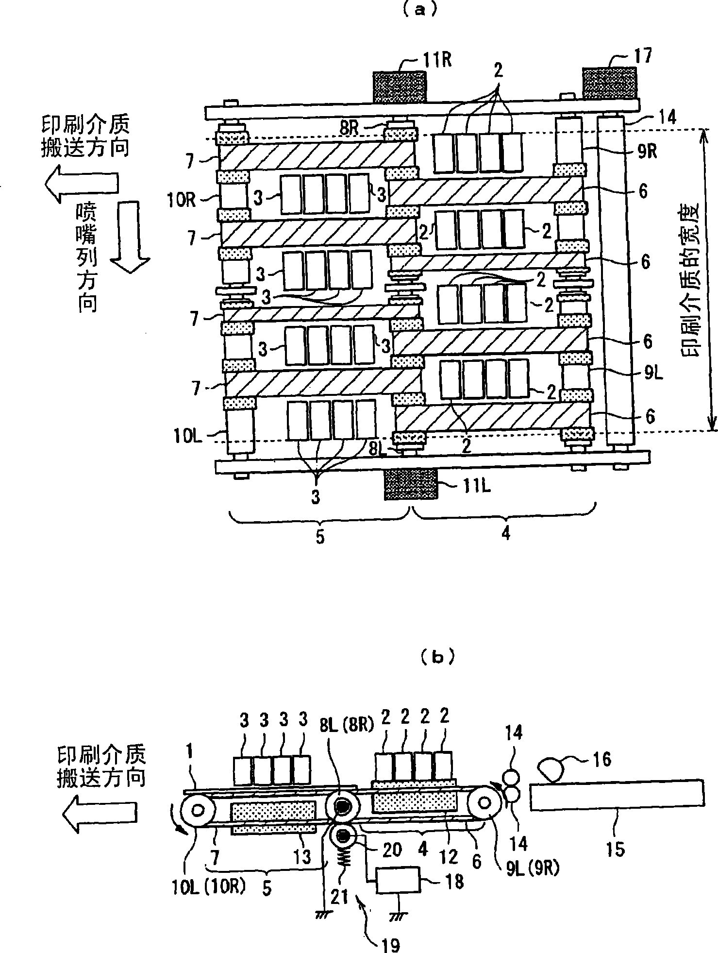
[0028] figure 1 is a schematic configuration diagram of an inkjet printer according to this embodiment, figure 1 a is its top view, figure 1 b is the front view. figure 1 In the figure, the printing medium 1 is conveyed from the right side to the left side of the figure along the direction of the arrow in the figure, showing a line head type inkjet printer that prints on the printing area during its conveyance. However, the inkjet head of this embodiment is not installed at only one location, but is installed at two locations.

[0029] The symbol 2 in the figure is the first inkjet head that is arranged on the upstream side of the conveying direction of the printing medium 1, and the symbol 3 is the second inkjet head that is similarly arranged on the downstream side. The second conveyance part 5 is provided below the second inkjet head 3 i...


PUM


Abstract

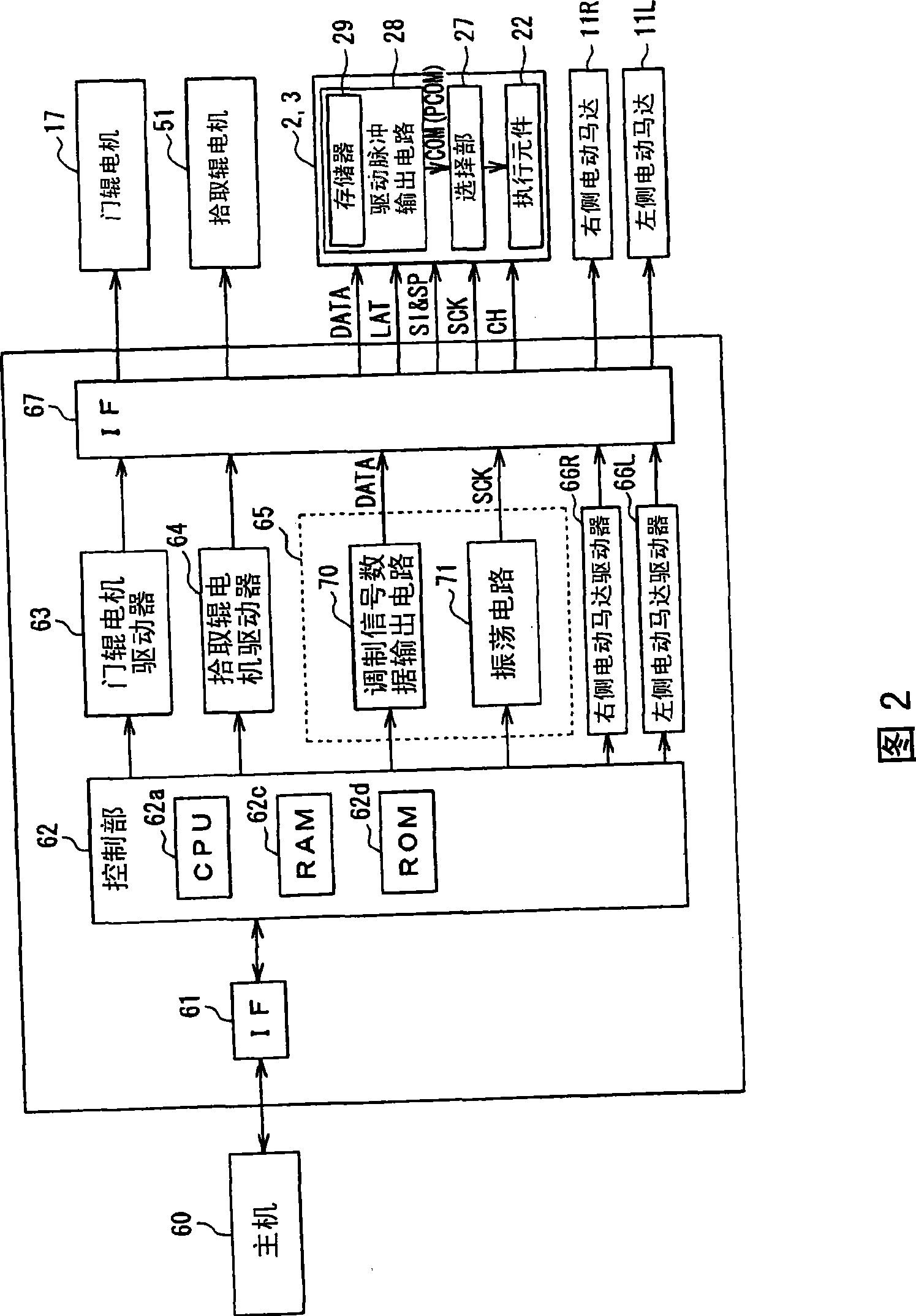
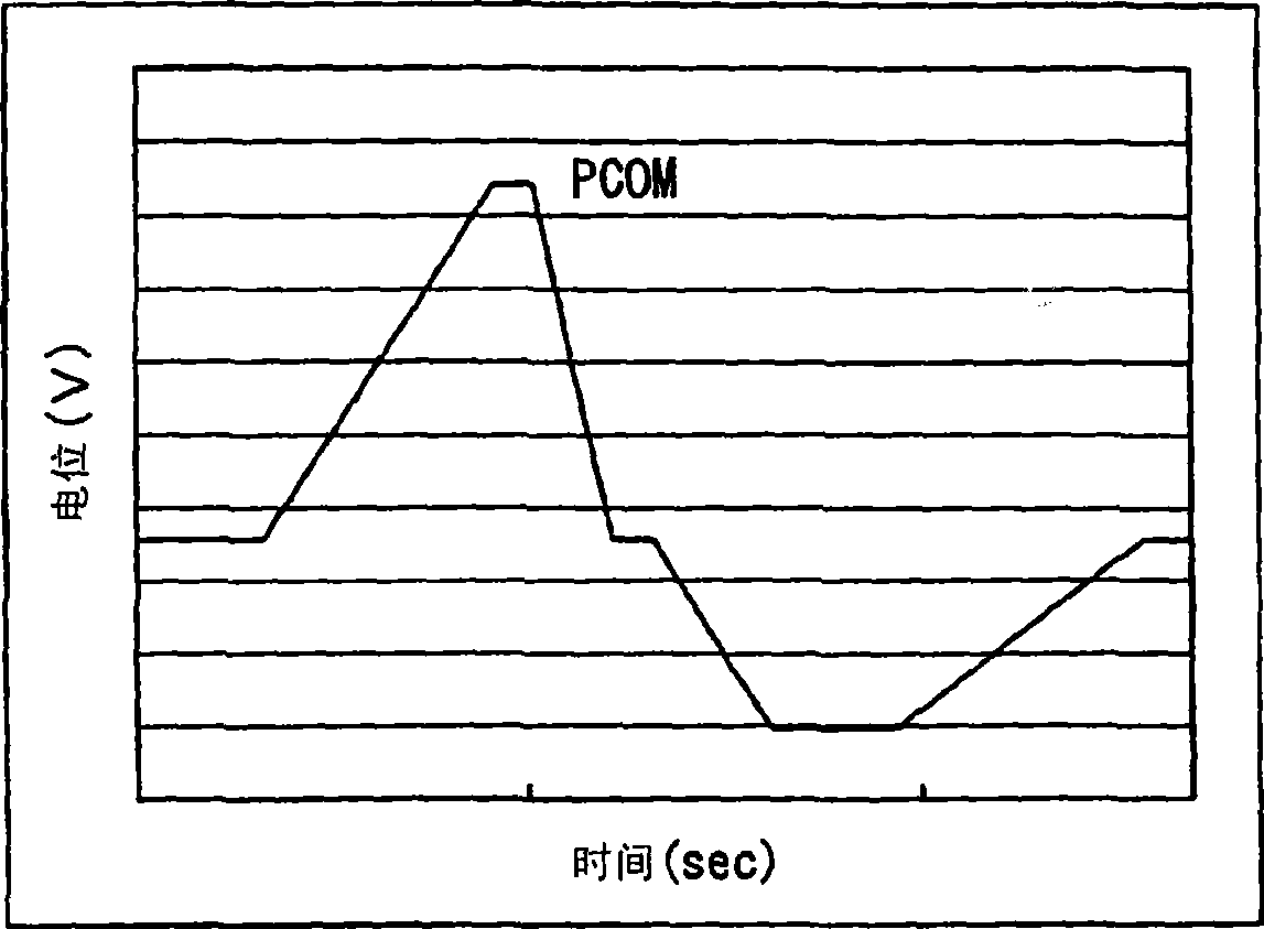
Modulating signal data (DATA) stored in a memory (29) is read out, and a modulating signal is outputted. This modulating signal is power-amplified by a digital power amplifier (25), and the power-amplified modulating signal is smoothed and is outputted as a driving pulse to an actuator (22). The modulating signal can be efficiently power-amplified by the digital power amplifier (25) excellent in the power amplifying efficiency. As a result, cooling means such as a cooling radiation plate for a transistor can be dispensed with so that a drive pulse output circuit (28) can be mounted on ink jet heads (2, 3). Thus, the transmission route of the actuator driving pulse can be shortened to suppress and prevent the waveform distortion of the drive pulse. The transfer of the modulating signal data (DATA) is performed at a low frequency. A driving pulse output circuit is mounted in a proper signal transmission mode on an ink jet head thereby to suppress and prevent the waveform distortion of an actuator driving pulse for discharging ink droplets.

Description

technical field [0001] The present invention relates to a head of an inkjet printer for drawing predetermined characters and images by ejecting tiny ink droplets of liquid ink of various colors from a plurality of nozzles and forming the fine particles (ink dots: ink dots) on a printing medium Driving device and head driving method. Background technique [0002] Since such inkjet printers are generally relatively cheap and can easily obtain high-quality color printed matter, they are widely used not only in offices, but also in general users along with the spread of personal computers and digital cameras. [0003] Such an inkjet printer generally uses a movable body called an ink cartridge carriage (carriage) having an ink cartridge and a printing head (also referred to as an inkjet head) integrally, along the print medium along with it. It moves back and forth in the direction intersecting the conveying direction, and at the same time ejects (jet) liquid ink droplets from ...

Claims


Application Information

Patent Timeline
Patent Type & Authority Applications(China)
IPC IPC(8): B41J2/045B41J2/055
CPCB41J2/04541B41J2/04581B41J2/04588B41J2/04593B41J2/04596
Inventor 铃木俊行田端邦夫新川修波多野智纪大岛敦
Owner SEIKO EPSON CORP
Learn More