
Method and apparatus for chromatic dispersion compensation of optimized wavelength passage

A technology of dispersion compensation and wavelength channel, which is applied in the field of optical communication, can solve problems such as non-optimal value of dispersion compensation, signal performance degradation, and should not adjust dispersion compensation, and achieve the effect of simple software implementation and avoiding oscillation phenomenon

Inactive Publication Date: 2009-02-18
ZTE CORP
View PDF2 Cites 17 Cited by
  • Summary
  • Abstract
  • Description
  • Claims
  • Application Information

AI Technical Summary

Problems solved by technology

Since the relationship between the amount of dispersion compensation and the difference between forward error correction 1 count and error correction 0 count is not completely monotonous, the dispersion compensation amount obtained by applying this patent method is not the optimal value
In addition, when the system is affected by the outside world, when the received optical power or optical signal-to-noise ratio changes, the difference between the forward error correction 1 count and the error correction 0 count will also change, and the forward error correction 1 count is not caused by dispersion. The amount of dispersion compensation should not be adjusted for the change of the difference between the error correction value and the error correction 0 count. If the above-mentioned patented method is used to adjust the dispersion compensation amount at this time, the signal performance may be degraded, and in severe cases, the normal communication of the business may be affected.

Method used

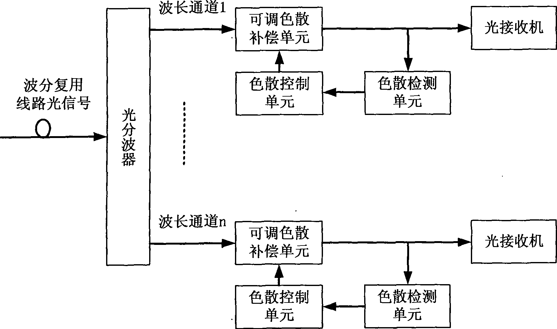
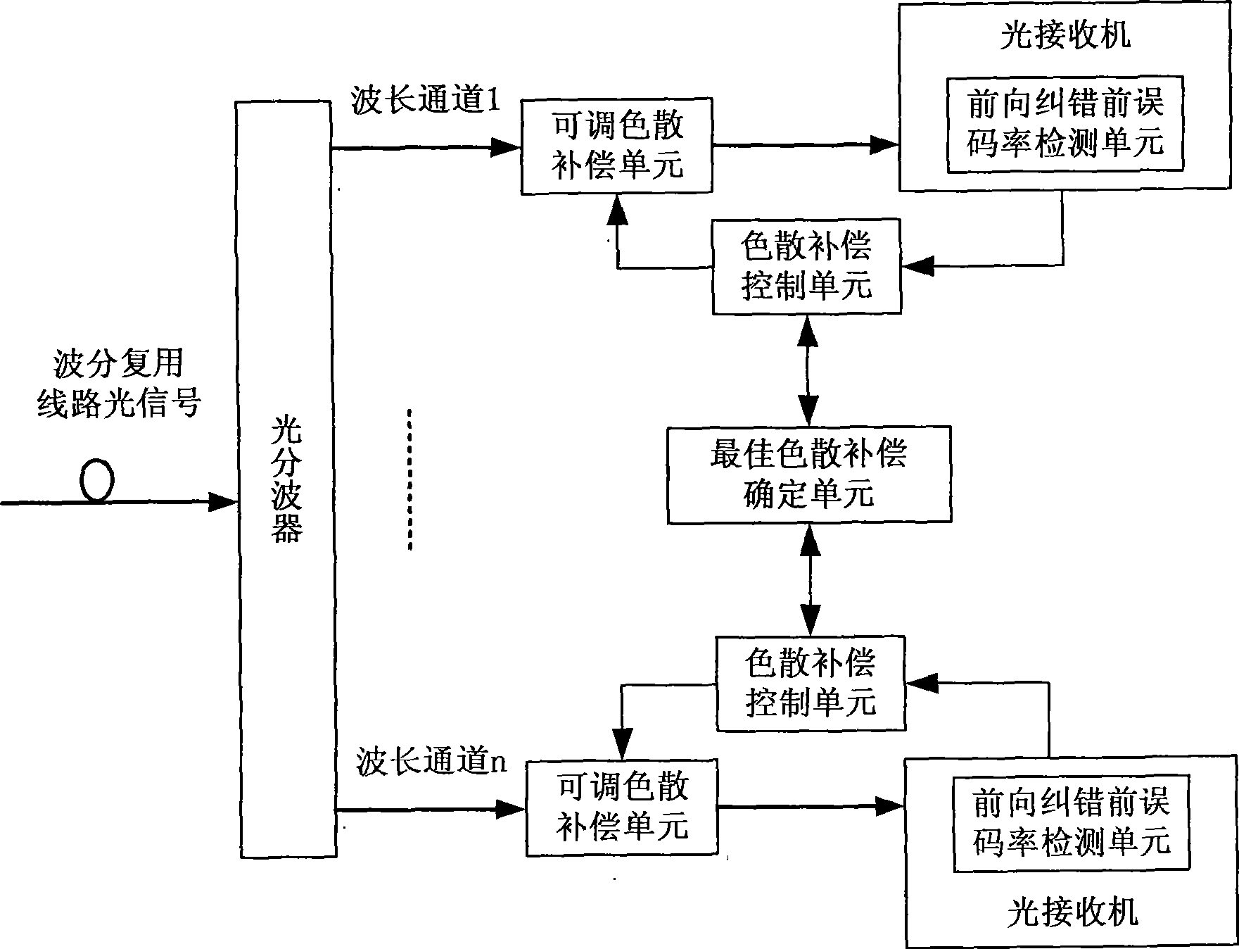
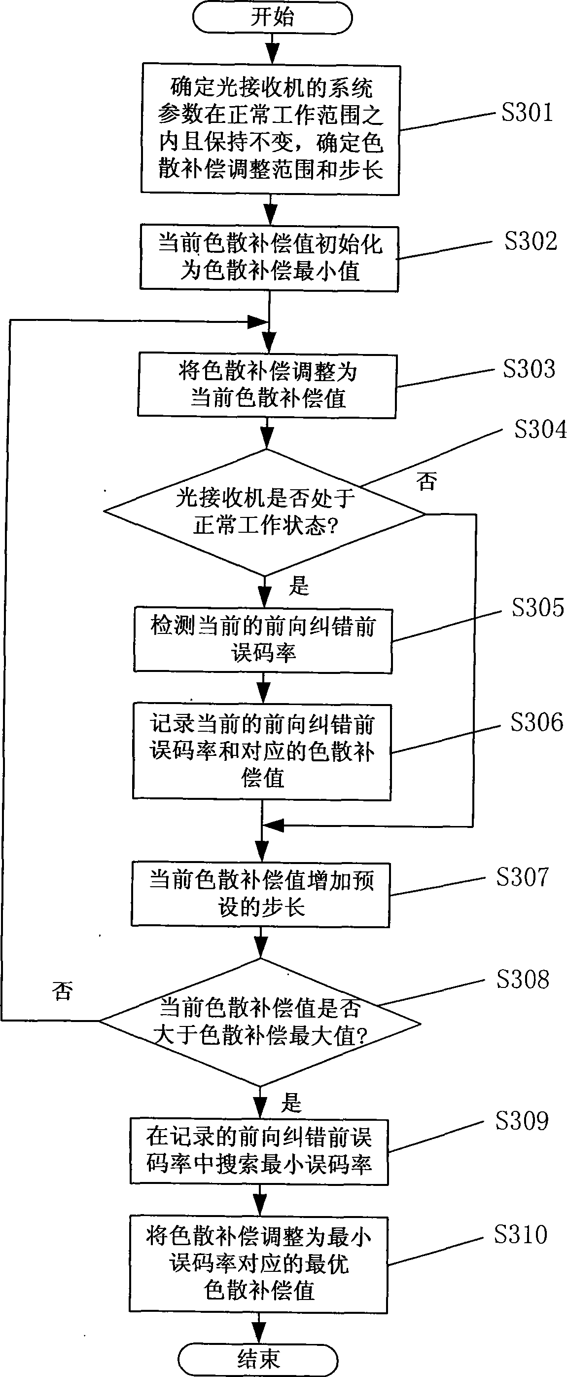

Image

  • Method and apparatus for chromatic dispersion compensation of optimized wavelength passage
  • Method and apparatus for chromatic dispersion compensation of optimized wavelength passage
  • Method and apparatus for chromatic dispersion compensation of optimized wavelength passage

Examples


Embodiment Construction

[0039] The method and device of the present invention will be described below with reference to the embodiments of the accompanying drawings.

[0040] The present invention is implemented from two aspects of the wavelength channel dispersion compensation device structure and the dispersion compensation value adjustment process.

[0041] The invention is a device for optimizing wavelength channel dispersion compensation, the structural features are as follows figure 2 shown, including:

[0042] The adjustable dispersion compensation unit is used to adjust the dispersion compensation value according to the instruction of the dispersion compensation control unit, and accurately compensate the dispersion of the single wavelength channel, and transmit the optical signal after dispersion compensation to the forward error correction in the optical receiver Front bit error rate detection unit. The tunable dispersion compensation unit can be realized by fiber Bragg grating technolog...


PUM


Abstract

The invention discloses a method for optimizing wavelength path dispersion compensation and a device thereof comprising: arranging an adjustable dispersion compensation unit before a light receiver for compensating the dispersion of a single wavelength path; adjusting the dispersion compensation value in a specified dispersion compensation adjustable range; respectively detecting a forward error rate of a forward error correction corresponding to different dispersion compensation values; searching the minimal value of the forward error rate of the forward error correction. The corresponding dispersion compensation value to the minimal value of the forward error rate is the optimum dispersion compensation. The method of the invention optimizes the dispersion compensation of the wavelength path based on the forward error rate of the forward error correction, obtains the optimum dispersion compensation and realizes the optimum dispersion compensation effect. The software implementation of the invention is easy, the shock phenomenon caused by frequently adjusting dispersion compensation value is avoided, and the device of the invention is suitable for popularization and application of the optical communication technique field relevant enterprises.

Description

technical field [0001] The invention relates to the technical field of optical communication, in particular to a method and a device for optimizing wavelength channel dispersion compensation in a wavelength division multiplexing optical transmission system. Background technique [0002] When the wavelength division multiplexing optical transmission system is used in long-distance applications, it is necessary to solve the problem of fiber dispersion. [0003] The typical dispersion tolerance of a single-wavelength channel rate of 10Gb / s optical signal is 800-1000 ps / nm. In the prior art, a fixed dispersion compensation fiber or module is placed on the optical fiber line to solve the optical fiber dispersion problem of this type of system. The typical dispersion tolerance of a single-wavelength channel rate of 40Gb / s optical signal is 60ps / nm, which is one sixteenth of the 10Gb / s optical signal. The method of fixed dispersion compensation cannot meet the requirements of compe...

Claims


Application Information

Patent Timeline
IPC IPC(8): H04B10/18H04B10/08H04J14/02H04B10/2525
Inventor 彭肖
Owner ZTE CORP
Learn More