Combination type prestressed concrete box beam

A concrete box girder and prestressed technology, applied in bridges, bridge materials, bridge construction, etc., can solve the problems of unsuitable cast-in-place prestressed concrete box girder, high construction cost of full-house support, and difficulty in erecting full-house support, etc. The effect of stable quality, ensuring consistency and saving construction period

Active Publication Date: 2009-02-18
SHENZHEN MUNICIPAL DESIGN & RES INST
View PDF0 Cites 8 Cited by
  • Summary
  • Abstract
  • Description
  • Claims
  • Application Information

AI Technical Summary

Problems solved by technology

The prestressed concrete box girder is usually a single-box single-chamber or single-box multi-chamber structure. The cast-in-place construction method is generally on-site full-wall support pouring construction. It is difficult to erect full-wall support in the busy road section, which seriously affects traffic; Prestressed concrete box girders have high construction costs for full support, so it is not suitable to use cast-in-place prestressed concrete box girders
Steel box girders are usually hoisted, and the construction is relatively simple and fast, but the cost of the project is high

Method used


Image

  • Combination type prestressed concrete box beam
  • Combination type prestressed concrete box beam
  • Combination type prestressed concrete box beam

Examples


Embodiment Construction

[0020] Embodiment; It can be clearly seen from Fig. 1 that the combined prestressed concrete box girder is composed of 2 prefabricated parts 1 with "τ" shape in cross section and 6 prefabricated parts 2 with "I" shape in cross section arranged in parallel.

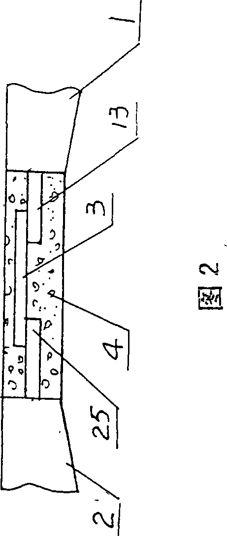
[0021] The ends of the upper top plate 11 and lower bottom plate 12 of the “τ” shaped prefabricated part 1 and the upper top plate 21 and lower bottom plate 22 of the “I” shaped prefabricated part 2 are arranged with exposed steel bars 13 (see Figure 2).

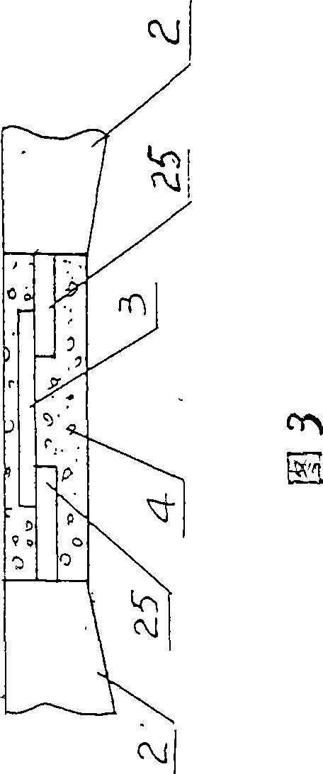
[0022] The upper top plate 21 and the lower bottom plate 22 of the "I" shape preform 2 are connected with the upper top plate 11 and the lower bottom plate 12 of the "τ" shape preform 1 / and with the upper top plate 21 and the lower bottom plate 2 of other "I" shape preforms 2 The butt ends 23 and 24 of the bottom plate 22 are arranged with exposed steel bars 25 (see FIGS. 2 and 3 ).

[0023] Arrange the upper top plate 21 ends and the lower bottom plate 22 ends of the si...


PUM


Abstract

A combined prestressed concrete box girder is characterized in that the combined prestressed concrete box girder is composed of two prefabricated pieces with T-shaped cross sections and a plurality of parallel prefabricated pieces with I-shaped cross sections. The two T-shaped prefabricated pieces are symmetrically arranged on both sides of the I-shaped prefabricated pieces. The Upper and lower crest slabs of the T-shaped prefabricated pieces are conglutinated through concrete with upper and lower crest slabs of the I-shaped prefabricated pieces, and the upper crest slabs and the lower crest slabs of the I-shaped prefabricated pieces are also conglutinated through concrete, forming a single-box multi-cavity prestressed concrete box girder structure. The combined prestressed concrete box girder can realize batch production in factories and solve the disadvantage of high cost of current oblique and curved steel box girders and inconvenient construction of cast-in-place prestressed concrete box girders. The concrete members of the combined prestressed concrete box girder produced through batch production in a factory are ensured to be consistent in size and specification. The combined prestressed concrete box girder is stable in quality, convenient in construction and can shorten construction period and meets the construction requirements of the high quality projects with smooth exteriors, compact interiors and straight lines.

Description

technical field [0001] The invention relates to building components, in particular to a combined prestressed concrete box girder. Background technique [0002] At present, for inclined girder bridges with large skew angles or curved girder bridges with small curvature radius, under the action of live load, the main girder section will generate a large torque, forming the mechanical characteristics of bending, shearing and torsion. The internal force distribution is extremely complex. At present, the commonly used structures are cast-in-place prestressed concrete box girder and steel box girder. The prestressed concrete box girder is usually a single-box single-chamber or single-box multi-chamber structure. The cast-in-place construction method is generally on-site full-wall support pouring construction. It is difficult to erect full-wall support in the busy road section, which seriously affects traffic; The prestressed concrete box girder has a high construction cost for t...

Claims


Application Information

Patent Timeline
IPC IPC(8): E01D2/04E01D101/28
Inventor 陈宜言王先前彭大文刘宁林国华彭栋木蔡明黄国兴蒙立军陈永昌朱秀兰许有胜陈朝慰
Owner SHENZHEN MUNICIPAL DESIGN & RES INST
Why Eureka
Try Eureka