
Earthing fault detection and control method for electromagnetic stirring system

An electromagnetic stirring and grounding fault technology, which is applied in the direction of measuring electricity, measuring devices, measuring electrical variables, etc., can solve the problem of accidental power failure of non-faulty electric stirring, reduce the yield of continuous casting slabs, and cannot quickly and accurately judge faulty electric stirring grounding Equivalence issues, to achieve accurate judgment, reduce impact, and ensure continuous and safe operation

Inactive Publication Date: 2011-05-25
武钢集团有限公司
View PDF0 Cites 0 Cited by
  • Summary
  • Abstract
  • Description
  • Claims
  • Application Information

AI Technical Summary

Problems solved by technology

However, the following problems generally exist in the fault handling mode of electric stirrer grounding: According to the existing grounding detection system and the program function of the controller, taking a 5-circuit 5-machine bloom continuous casting machine as an example, when a ground fault occurs in one of the 5 circuits When a fault occurs, the judgment of the system ground fault is automatically carried out in the order of 1 to 5 circuits, and the fault circuit and the first few circuits of the fault circuit are affected
This method of fault detection and maintenance is likely to cause accidental power-off of non-faulty electric stirrers, and cannot quickly and accurately determine the ground phase of faulty electric stirrers, which seriously affects the normal electric stirrer process and reduces the yield of continuous casting slabs

Method used


Image

  • Earthing fault detection and control method for electromagnetic stirring system
  • Earthing fault detection and control method for electromagnetic stirring system
  • Earthing fault detection and control method for electromagnetic stirring system

Examples


Embodiment Construction

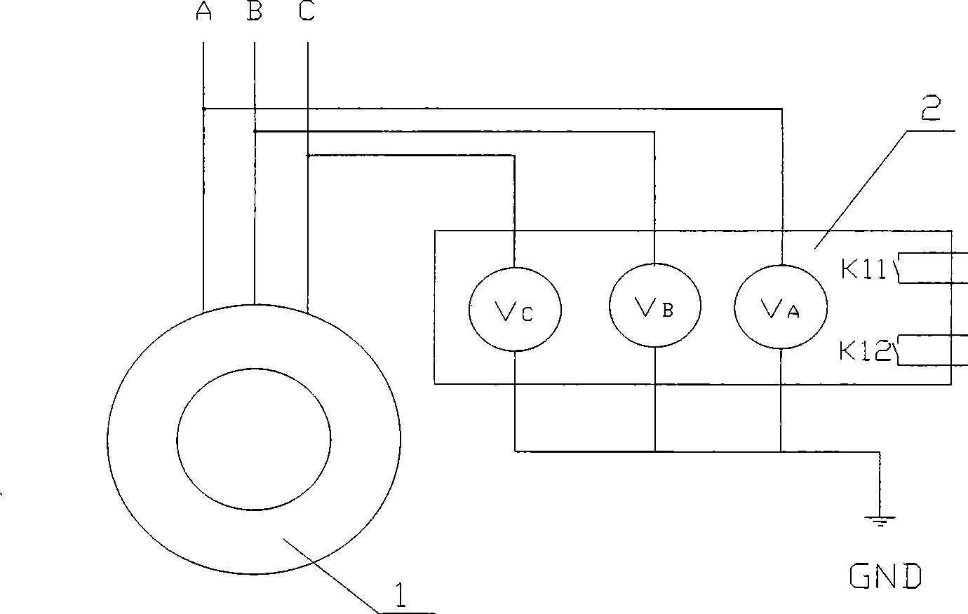
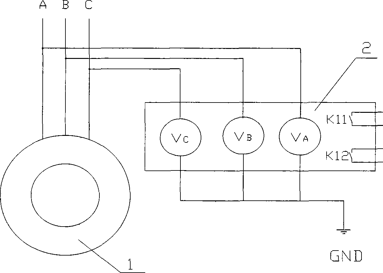
[0015] Such as figure 1 As shown, for a certain circuit of the multi-circuit and multi-machine electromagnetic stirring system, the A, B, and C three-phase cables of the electromagnetic stirring coil 1 are connected in series with the intelligent instrument 2 at the outlet end of the inverter cabinet of the electromagnetic stirrer. Smart Meter 2 is a general-purpose meter for voltage measurement, which includes V A , V B , V C The three voltmeters correspond to the real-time detection of A, B, and C three-phase voltage values. The first relay switches K11 and K12 are respectively connected to different input points of the PLC control module of the electromagnetic stirring system, and the second relay switch K12 controls the alarm signal light and the buzzer through the PLC of the electromagnetic stirring system. When one of the phases of the electric stirring equipment in a certain circuit is grounded, the ground-to-ground voltage value will be greatly reduced, and the gro...


PUM


Abstract

The invention relates to the earth fault loop detection and control field of an electromagnetic stirring system of a continuous casting machine in steel-making industry and provides an earth fault loop detection and a control method of the electromagnetic stirring system. Intelligent instruments are respectively serially connected with earth points of three-phase cables of each electromagnetic coil of an electric stirring machine of the electromagnetic stirring system for detecting the voltage of each phase of the coil; and relay switches in the intelligent instruments are connected with a switch amount interface of a control module of the electromagnetic stirring system. When one phase of a certain coil of the electric stirring machine is earthed, the voltage to earth of the earthed phase can be greatly reduced correspondingly, and the voltages to earth of the other phases can be increased. Accordingly, the method can rapidly and accurately determine earth fault, and correspondingly sends an alarm or carries out circuit switch tripping. The method can rapidly and accurately determine earth fault of the electric stirring machine to reduce the influences on other casting loops, andcan effectively make a prediction before the earth fault occurs. The method can be generalized and applied in steel-making industry.

Description

technical field [0001] The invention relates to the field of detection and control of a grounding fault circuit of an electromagnetic stirring system of a continuous casting machine in the steelmaking industry. Background technique [0002] Most of the bloom continuous casters in the steelmaking industry have adopted the mold electromagnetic stirring device. However, the following problems generally exist in the fault handling mode of electric stirrer grounding: According to the existing grounding detection system and the program function of the controller, taking a 5-circuit 5-machine bloom continuous casting machine as an example, when a ground fault occurs in one of the 5 circuits When a fault occurs, the judgment of the system grounding fault is automatically carried out in the order of 1 to 5 circuits, and the fault circuit and the first few circuits of the fault circuit are affected. For example, if the coil of loop 2 is grounded, only loop 1 and loop 2 will be affect...

Claims


Application Information

Patent Timeline
Patent Type & Authority Patents(China)
IPC IPC(8): H02H3/08G01R31/02
Inventor 李鹏焦黎童健民罗辉陈代任李振华高志利余召其袁章峰安春林
Owner 武钢集团有限公司
Learn More