
Push button switch

A switch and shell technology, applied in the field of buckle switches, can solve the problems of unstable contact state of peripheral fixed contacts, difficulty in ensuring contact pressure, and reduced switch performance, and achieve the effect of superior switch performance

Inactive Publication Date: 2009-02-11
ALPS ALPINE CO LTD
View PDF1 Cites 9 Cited by
  • Summary
  • Abstract
  • Description
  • Claims
  • Application Information

AI Technical Summary

Problems solved by technology

In this way, the lifting force acts on the raised portion of the movable contact, and it is difficult to ensure the desired contact pressure between the raised portion of the movable contact and the surrounding fixed contacts.
That is, the contact state between the raised portion of the movable contact and the surrounding fixed contacts is unstable, and the switching performance is degraded.

Method used


Image

  • Push button switch
  • Push button switch
  • Push button switch

Examples


Embodiment Construction

[0032] The best mode for implementing the snap switch of the present invention will be described with reference to the drawings.

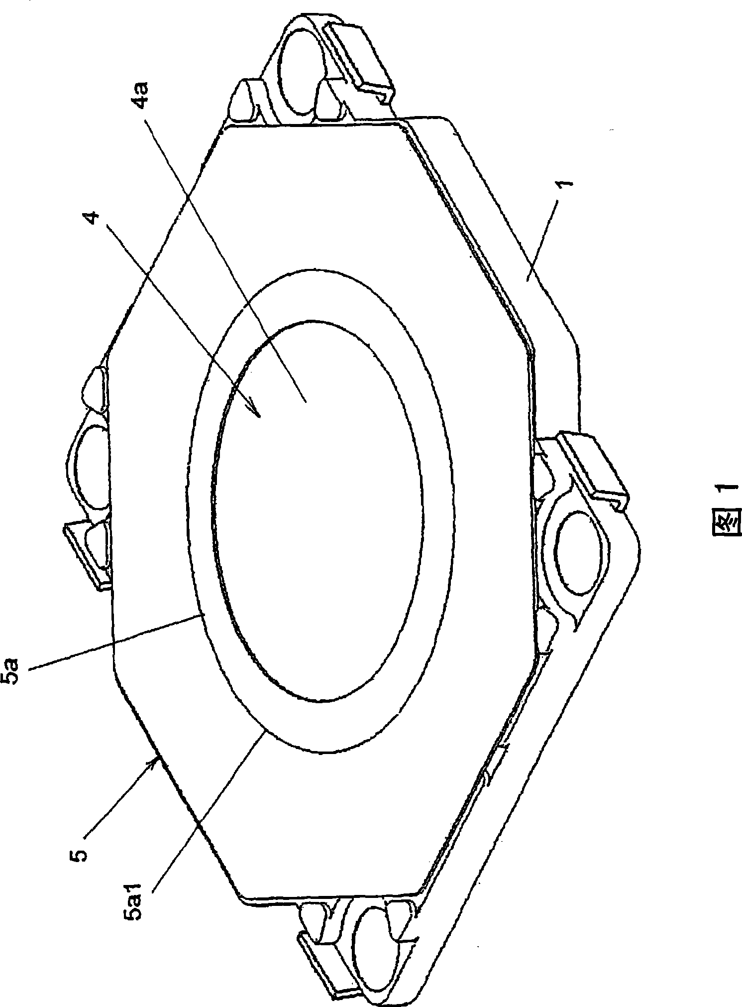
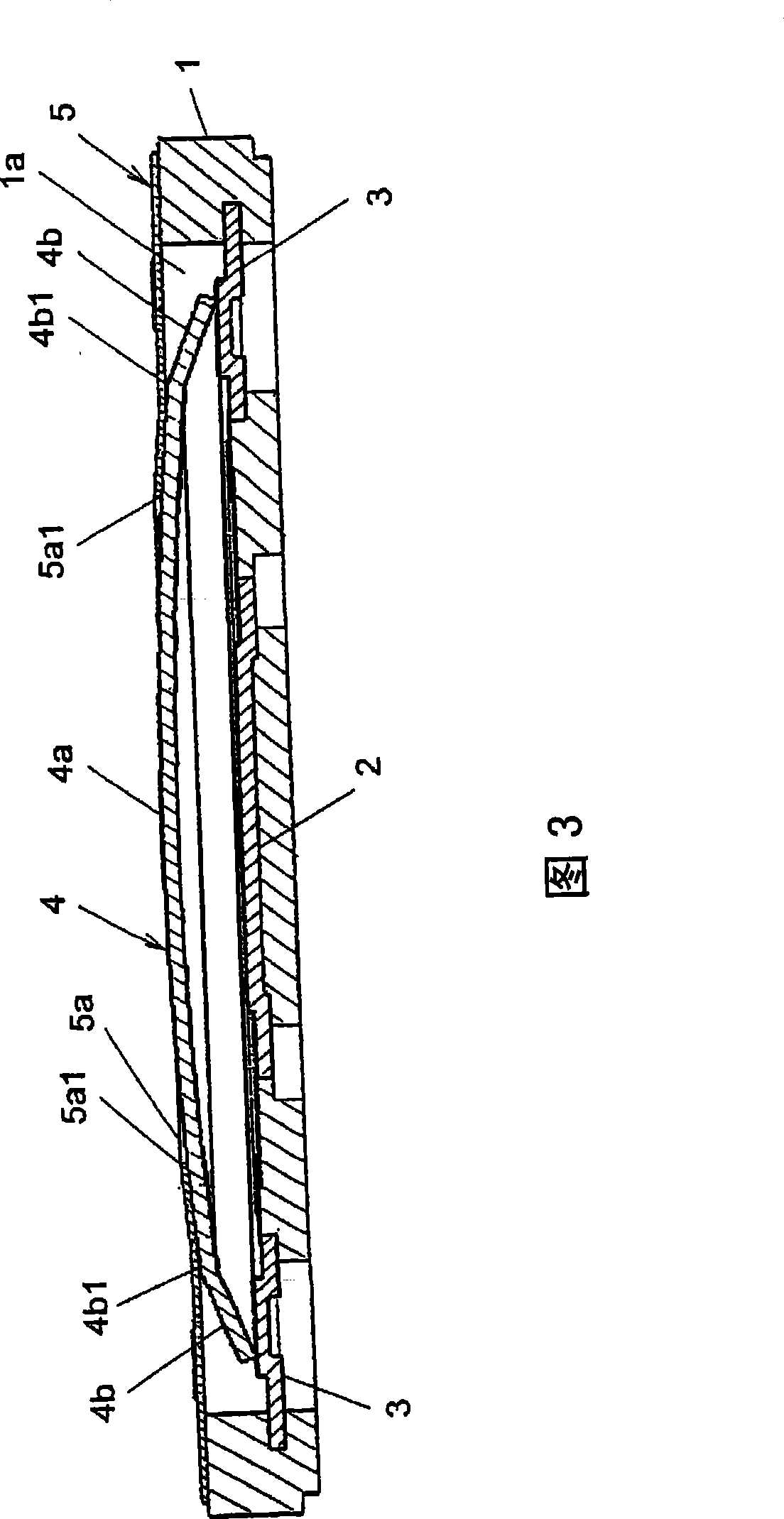
[0033] FIG. 1 is a perspective view showing an embodiment of a push switch according to the present invention, figure 2 It is an exploded perspective view of this embodiment, and FIG. 3 is a longitudinal sectional view of this embodiment.

[0034] As shown in these FIGS. 1 to 3 , in this embodiment, there are: a housing 1 with an opening on the upper surface, a housing portion 1 a, and made of an insulating material such as synthetic resin; The central fixed contact 2 and the peripheral fixed contacts 3. In addition, there is a movable contact 4 housed in the housing portion 1 a of the case 1 and always conducting with the peripheral fixed contacts 3 and selectively conducting with the central fixed contact 2 .

[0035] The movable contact 4 is formed by stamping a conductive thin metal plate made of phosphor bronze or stainless steel with a surf...


PUM


Abstract

The invention relates to a pressing-fastening switch capable of reducing hanging force applied on a standing section of a movable contact from an adhering piece when pressing the movable contact. The switch is provided with a movable contact (4) always conducting with a circumjacent fixed contact (3) and selectively conducting with a central fixed contact (2), and an adhering piece (5) capable of holding the movable contact (4) in a housing (1) in counter revolution manner, the movable contact (4) comprises a swelling section (4a) capable of reversing, a standing section (4b) formed on periphery of the swelling section (4a), the adhering piece (5) is provided with a through hole, such as a circular hole (5a) on position corresponding with the swelling section (4a) of the movable contact (4), the adhering piece (5) is plastered on the movable contact (4) and the housing (1), such that the periphery section (5a1) of the circular hole (5a) is at position nearer the swelling section (4a) than that of pressing-curing starting point (4ba) of the periphery section of the standing section (4b) and the swelling section (4a).

Description

technical field [0001] The invention relates to a push-button switch which can be pressed to make the movable contact reverse and separate from the fixed contact. Background technique [0002] As such a conventional technique, there exists a technique shown in patent document 1. In this prior art, there is a casing with an upper opening, a bottom insert-molded central fixed contact, and a peripheral fixed contact, and the casing is accommodated in the housing portion, always conducts with the peripheral fixed contacts, and selectively connects with the central fixed contacts. Conductive arched movable contacts. The movable contact has a bulge disposed opposite to the central fixed contact and a skirt portion formed on the periphery of the bulge to always conduct with the peripheral fixed contacts and stand up at a predetermined angle. That is to say, stand up. In addition, in order to hold the movable contact on the case, and to prevent the intrusion of external air and d...

Claims


Application Information

Patent Timeline
Patent Type & Authority Applications(China)
IPC IPC(8): H01H13/52H01H13/06H01H13/12
Inventor 小田岛正彦高桥一成佐藤秀隆
Owner ALPS ALPINE CO LTD
Learn More