
Back light module unit and LCD device

A technology for liquid crystal display devices and backlight modules, applied in light guides, optics, optical components, etc., can solve problems such as poor brightness of backlight modules, and achieve the effects of low viscosity requirements, reduced thickness, and improved light output brightness

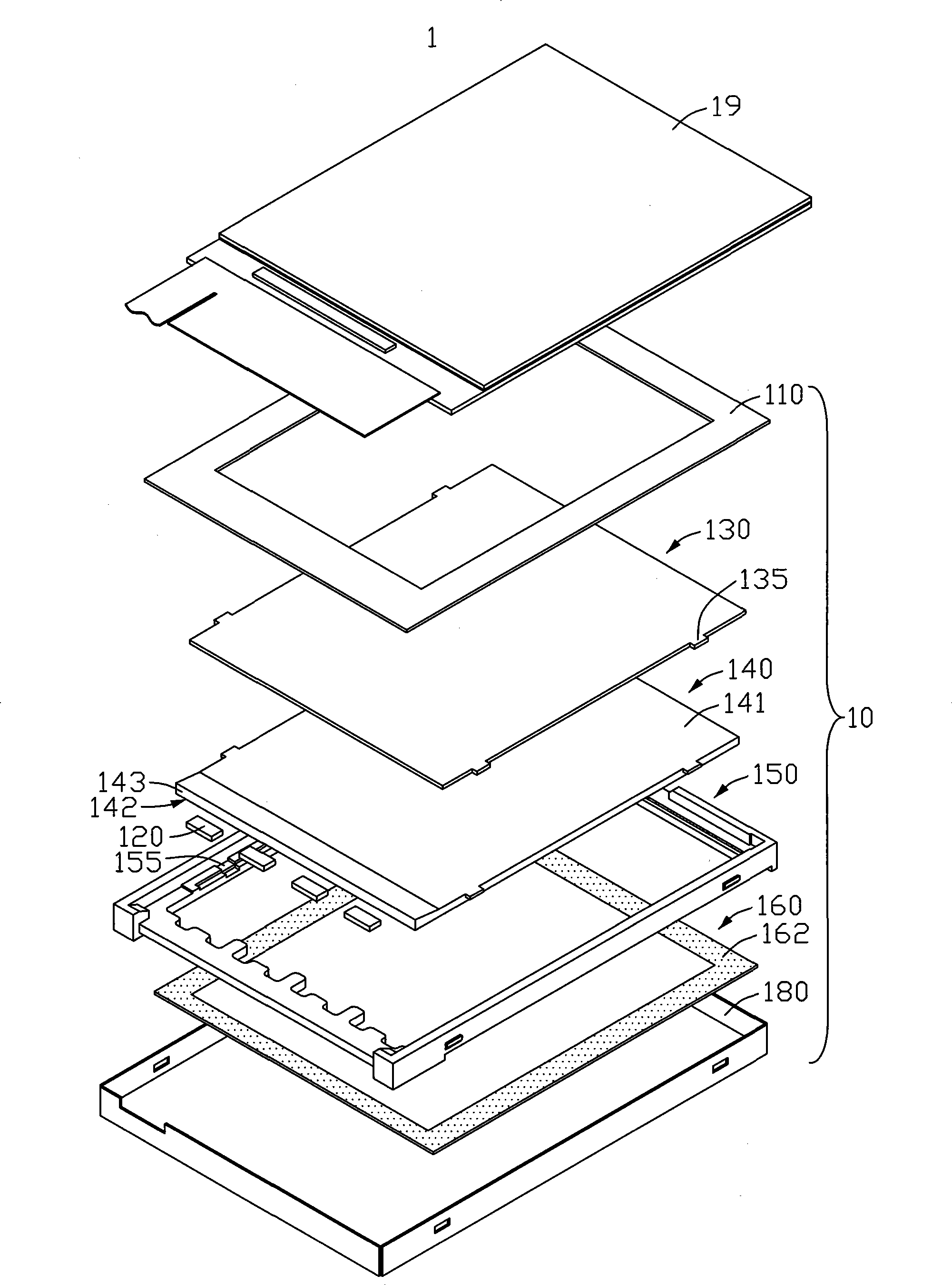
Inactive Publication Date: 2009-02-11
INNOCOM TECH (SHENZHEN) CO LTD +1
View PDF0 Cites 8 Cited by
  • Summary
  • Abstract
  • Description
  • Claims
  • Application Information

AI Technical Summary

Problems solved by technology

[0007] In order to solve the problem of poor brightness of backlight modules in the prior art, it is necessary to provide a backlight module with better brightness

Method used


Image

  • Back light module unit and LCD device
  • Back light module unit and LCD device
  • Back light module unit and LCD device

Examples


Embodiment Construction

[0024] see Figure 5 , is a schematic perspective view of the first embodiment of the liquid crystal display device of the present invention. The liquid crystal display device 2 includes a liquid crystal panel 29 and a backlight module 20 adjacent to the liquid crystal panel 29 .

[0025] The backlight module 20 includes a light-shielding tape 210 , a light source 220 , an optical film set 230 , a light guide plate 240 , a plastic frame 250 , a reflector 260 and a metal back plate 280 . The light guide plate 240 includes a light-emitting surface 241, a bottom surface 242 opposite to the light-emitting surface 241, a light-incident surface 243 intersecting the light-emitting surface 241, two opposite side surfaces 244 connected to the light-incident surface 243, and a bottom surface 242 disposed on the light-emitting surface 241. A plurality of protrusions 245 on two opposite sides 244 . The plastic frame 250 includes a plurality of receiving grooves 255 matched with the plur...


PUM


Abstract

The invention relates to a backlight module and a liquid crystal display (LCD) adopting the backlight module. The backlight module includes a light guide plate, a reflection plate and a metal back plate for accommodating the light guide plate and the reflection plate. The metal back plate includes a bossed bottom board; the reflection plate is arranged adjacent to the bottom board; and the boss corresponds to the edge of the reflection plate and applies the acting force onto the reflection plate for the contact of the reflection plate and the light guide plate.

Description

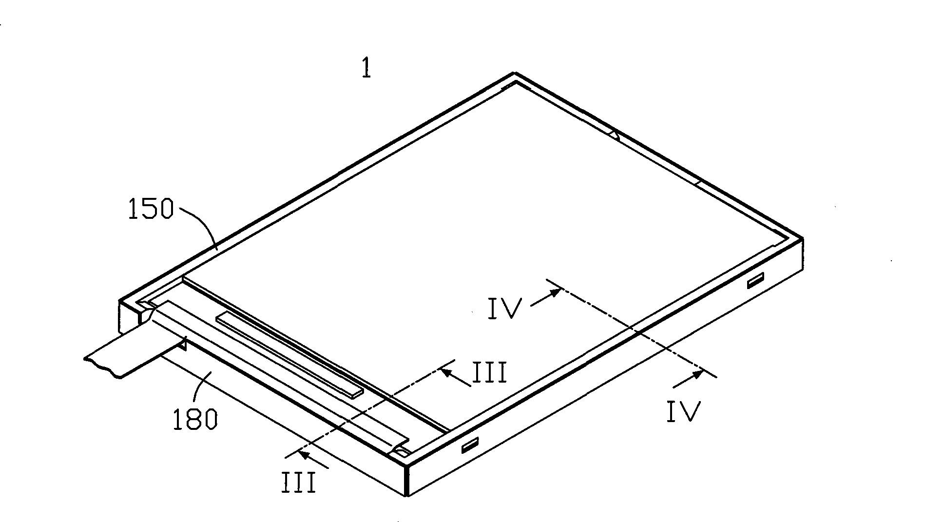
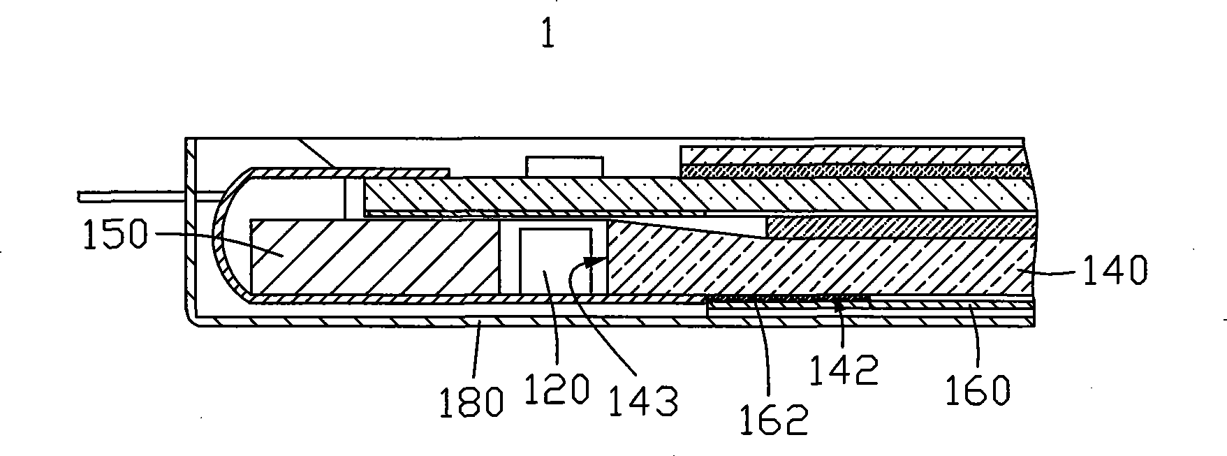
technical field [0001] The invention relates to a backlight module and a liquid crystal display device using the backlight module. Background technique [0002] Since the liquid crystal panel is a non-self-illuminating display device, in order to achieve the display purpose, it is necessary to provide a light source device for the liquid crystal panel to realize its display function, such as a backlight module, whose function is to provide the liquid crystal panel with sufficient brightness and uniform distribution. flat light. [0003] see figure 1 , is a three-dimensional exploded schematic diagram of a liquid crystal display device 1 in the prior art. The liquid crystal display device 1 includes a liquid crystal panel 19 and a backlight module 10 adjacent to the liquid crystal panel 19 . [0004] The backlight module 10 includes a light shielding tape 110 , a light source 120 , an optical film set 130 , a light guide plate 140 , a plastic frame 150 , a reflector 160 an...

Claims


Application Information

Patent Timeline
Patent Type & Authority Applications(China)
IPC IPC(8): G02F1/13357G02B6/00G02F1/1335
CPCG02F2201/46G02F1/133308G02F1/133608G02F2001/133314G02F1/133314
Inventor 唐志舜
Owner INNOCOM TECH (SHENZHEN) CO LTD
Learn More