Floating connection device between hydraulic power unit gear box and oil pump for engineering ship

A hydraulic pump station and coupling device technology, which is applied in infrastructure engineering, couplings, motor vehicles, etc., can solve the misalignment of the output shaft of the gearbox of the hydraulic pump station and the shaft of the high-pressure oil pump group, damage to the spline teeth of the hydraulic oil pump, and all In order to solve the problems such as the failure of normal construction of the ship, it can achieve the effect of easy guarantee of processing accuracy, convenient lubrication and cooling, and easy guarantee of hardness

Active Publication Date: 2009-02-11
SHANGHAI QIYAO HEAVY IND CO LTD
View PDF0 Cites 4 Cited by
  • Summary
  • Abstract
  • Description
  • Claims
  • Application Information

AI Technical Summary

Problems solved by technology

At the same time, the working characteristics of the engineering ship hydraulic pump station are constantly changing working conditions. The deformation of the working hull of the engineering ship will inevitably cause the output shaft of the hydraulic pump station gearbox and the shaft of the high-pressure oil pump group to be misaligned.
These factors make the working environment of the spline under the direct spline connection mode very bad. The friction and movement under high load will cause the accumulated high temperature on the tooth surface, thereby reducing the strength of the tooth surface and causing tooth surface wear, which will eventually cause damage to the spline teeth.
In actual use, there have been many serious accidents such as damage to the gear box of the hydraulic pump station and the spline teeth of the hydraulic oil pump, resulting in the failure of the normal construction of the whole ship

Method used


Image

  • Floating connection device between hydraulic power unit gear box and oil pump for engineering ship
  • Floating connection device between hydraulic power unit gear box and oil pump for engineering ship
  • Floating connection device between hydraulic power unit gear box and oil pump for engineering ship

Examples


Embodiment Construction

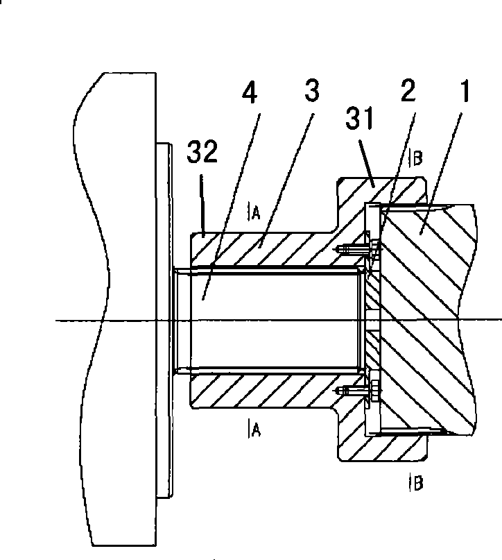
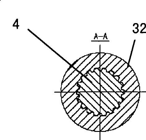
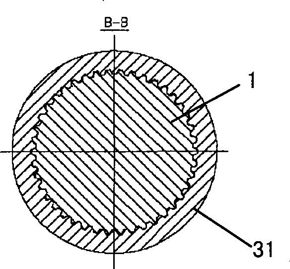
[0019] Also refer to figure 1 , figure 2 and image 3 , An embodiment of the present invention includes a gearbox output shaft head 1, a baffle plate 2, a floating spline sleeve 3 and an oil pump shaft head 4.

[0020] The gearbox output shaft head 1 has external splines, and the oil pump shaft head 4 also has external splines. The floating spline sleeve 3 includes a first key sleeve 31 and a second key sleeve 32, and the first key sleeve 31 and the second key sleeve 32 are connected. The first key casing 31 and the second key casing 32 are respectively formed with internal splines. The spline parameters of the first key sleeve 31 correspond to the spline parameters of the external splines of the output shaft head 1 of the gearbox, and the spline parameters of the second key sleeve 32 correspond to the spline parameters of the external splines of the oil pump shaft head 4 . The first key sleeve 31 of the floating spline sleeve 3 is splined to the gearbox output shaft hea...


PUM


Abstract

The invention relates to a floating connection device of a gear case and an oil pump of a hydraulic pump station in engineering vessels; the floating connection device comprises an output shaft head of the gear case with an external spline, a shaft head of the oil pump with an external spline and a floating spline housing with a first spline housing and a second spline housing; the first spline housing is connected with the second spline housing, the first spline housing is formed with an internal spline and the second spline housing is also formed with an internal spline; wherein, the first spline housing is connected with the spline at the output shaft head of the gear case, and the second spline housing is connected with the spline at the shaft head of the oil pump, so that the output shaft head of the gear case can be connected with the shaft head of the oil pump in a floating way.

Description

technical field [0001] The invention relates to a transmission device in a hydraulic system of an engineering ship, in particular to a coupling device between a gear box of a hydraulic pump station and an oil pump in the hydraulic system of an engineering ship. Background technique [0002] The hydraulic pump station is one of the key equipment for engineering ships such as cutter suction dredgers and piling ships. Taking the power transmission system of a cutter suction dredger as an example, it generally consists of the following four sets of sub-transmission systems that are independent and closely related to each other: in-cabin mud pump transmission system, hydraulic pump station transmission system, and underwater mud pump transmission system and reamer drive system. The transmission system of the hydraulic pump station is used to transmit the power of the diesel engine to the high-pressure hydraulic oil pump to provide power for the hydraulic devices such as the moto...

Claims


Application Information

Patent Timeline
Patent Type & Authority Applications(China)
IPC IPC(8): F16D3/06B63B35/00E02F3/92E02D7/00
Inventor 常震罗龚春全严忠胜王天驰董鹏李强徐翔江瑞田刘渊卢永文
Owner SHANGHAI QIYAO HEAVY IND CO LTD
Why Eureka
Try Eureka