Closed type static pressure turntable and bidirectional piston clamping mechanism thereof

A technology of clamping mechanism and hydrostatic turntable, applied in metal processing machinery parts, large fixed members, metal processing equipment, etc. Problems such as poor capacity, to achieve the effect of smooth rotation, small friction coefficient, and increased bearing capacity

Active Publication Date: 2009-02-11
通用技术集团沈阳机床有限责任公司
View PDF0 Cites 13 Cited by
  • Summary
  • Abstract
  • Description
  • Claims
  • Application Information

AI Technical Summary

Problems solved by technology

[0004] The purpose of the present invention is to provide a closed static pressure turntable and its two-way piston clamping mechanism, which solves the problem that the large and medium-sized CNC machine tool has a closed static pressure structure rotary table that cannot control the floating amount when the static pressure floats
[0006] In order to solve the problems of the traditional rotary table, such as poor ability to bear eccentric loads, high friction, difficult to rotate at high speed, and uncontrolled floating

Method used


Image

  • Closed type static pressure turntable and bidirectional piston clamping mechanism thereof
  • Closed type static pressure turntable and bidirectional piston clamping mechanism thereof
  • Closed type static pressure turntable and bidirectional piston clamping mechanism thereof

Examples


Embodiment Construction

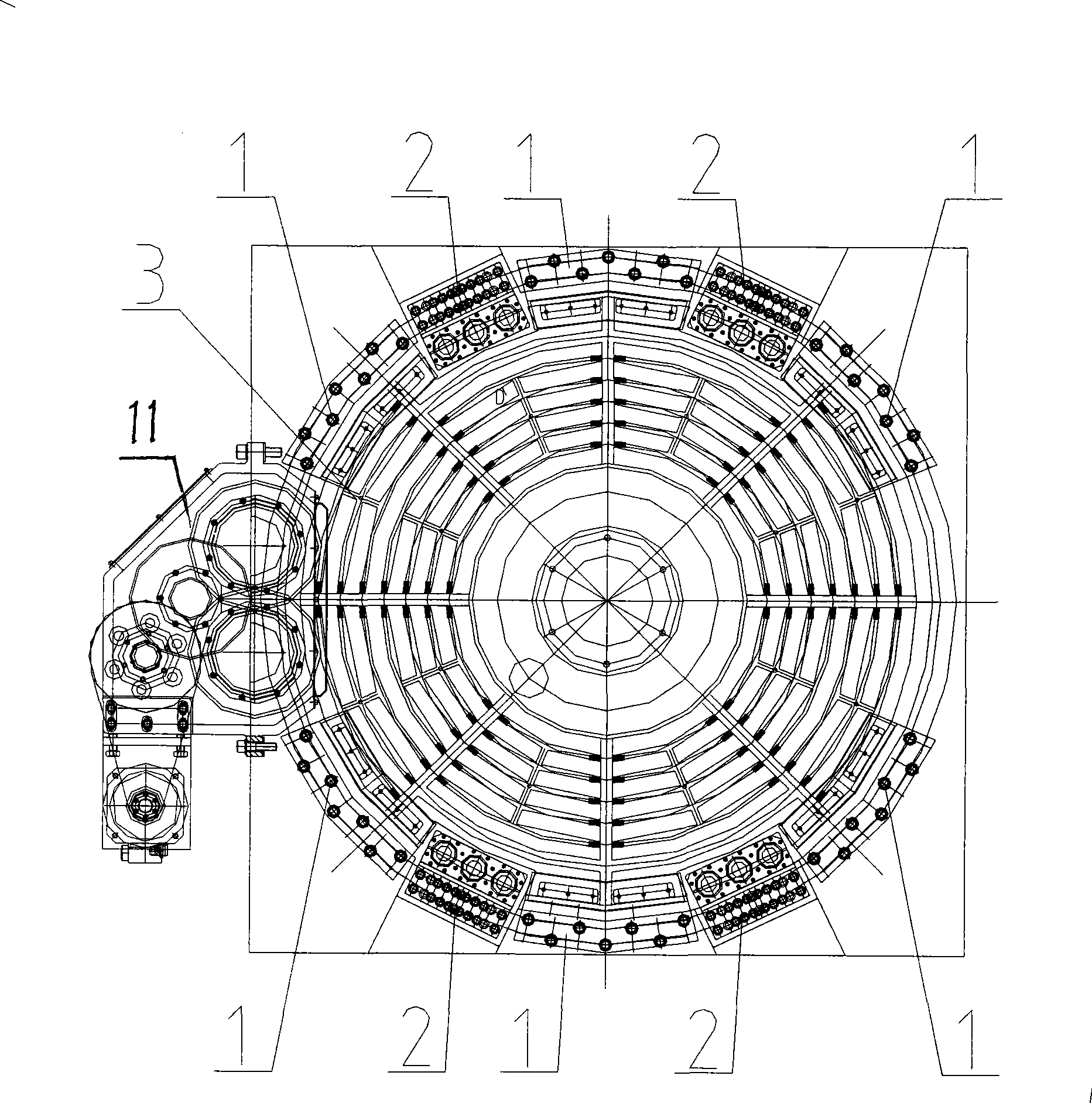
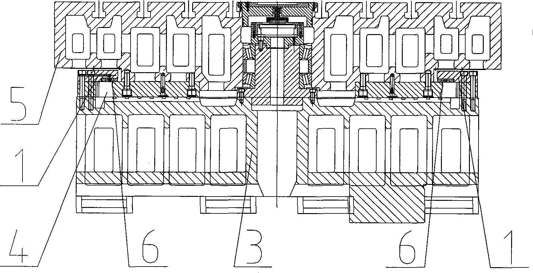
[0014] The closed static pressure turntable and its two-way piston clamping mechanism are equipped on large and medium-sized CNC machine tools, including a multi-head pump supplied by a hydraulic pump station, and a piston drive device. Type static pressure structure, such as figure 2 : The large ring gear 4 is installed on the lower part of the worktable turntable body 5, and the inner hole of the lower cylinder of the worktable turntable body 5 and the large ring gear 4 adopts a coaxial base hole system for clearance fit, and falls on the sliding seat 3 together. 4. In the gap protruding from the turntable body 5 of the worktable, the pressure plate 1 and the clamping mechanism 2 are arranged at intervals, see figure 1 : Evenly distributed within the range of 135° on both sides of the driving device, four clamping mechanisms 2 are arranged between the pressure plates 1 at intervals to form a relatively high flatness and smoothness. The bottom surface of the large ring gear...


PUM


Abstract

The invention relates to a close type static pressure rotary table and a double way piston clamping mechanism thereof, which are assembled on a large or medium size numerical control machine tool. The close type static pressure rotary table is characterized in that the lower column of the rotary table body of a work bench and the inner bore of a bull gear adopt clearance fit in the form of coaxial basic hole, and laid on a slide seat together, and a guide pair with inverse pressure formed on the upper surface of a static pressure oil chamber is machined on the bottom surface of the bull gear with higher flatness and fineness and the slide seat; a pressure plate and a double way piston clamp are arranged on the periphery at intervals, butt-jointed static pressure oil chambers of the pressure plate and the static pressure block embedded on the pressure plate are communicated with the oil outlet pipe of a quantitative multi-head pump, so as to respectively provide static oil for the upper surface and the lower surface of the guide pair; the upper part and the lower part of the double way piston clamp are arranged above the bull gear and under the bull gear, a drive unit formed by a gear reducer is installed on the side surface of the slide seat, and the two gears of the drive unit are meshed with the bull gear, so as to transmit the torque and drive the work bench to revolve. The invention not only has the advantages of traditional open type static pressure rotary tables, but also has the advantages of strong offset load bearing ability and steady float height due to the close type structure, the load bearing ability of the large or medium size numerical control machine tool provided with the work bench is increased, the machining accuracy is improved, the installation work hour and the maintenance work hour are reduced, and the cost is decreased.

Description

technical field [0001] The invention relates to mechanical manufacturing equipment, that is, a closed static pressure turntable and a clamping mechanism in a machine tool. technical background [0002] The development direction of modern CNC machine tools is the "three highs" trend of high speed, high torque, and high load capacity, and the requirements for guide rails, which are an important part of machine tools, are also constantly improving: high precision, high rigidity and large load-carrying capacity, friction coefficient Low. Therefore, as the most commonly used traditional steel-coated plastic guide rail pairs and rolling linear guide rails, they cannot fully meet the above requirements, and have gradually withdrawn from the preferred range of modern machine tool designers. Although the new heavy-duty linear guide rail can meet the requirements of the linear motion of the machine tool, it is difficult to meet the requirements of the circular guide rail of the rotar...

Claims


Application Information

Patent Timeline
IPC IPC(8): B23Q1/25
Inventor 郭鑫张继昌徐永明王颖兰军杨天博
Owner 通用技术集团沈阳机床有限责任公司
Why Eureka
Try Eureka