Oblique crankshaft Variable plunger pump

A variable plunger and crankshaft technology, applied in the field of hydraulic power components, can solve the problems of large friction loss, large oil loss and large pressure loss of the main transmission device

Inactive Publication Date: 2009-02-04
谌小堰
View PDF1 Cites 6 Cited by
  • Summary
  • Abstract
  • Description
  • Claims
  • Application Information

AI Technical Summary

Problems solved by technology

[0002] At present, there are axial flow distribution devices in the structure of the radial variable plunger pump and the swash plate axial variable pump, such as CN200720031562.8, which consists of a housing, a pump cover, a flow distribution shaft, a drive shaft, a rotor, a stator, Composed of sliding shoes, limit valves and variable control valves, the internal distribution shaft, rotor, stator and other structures of this pump are relatively complex, and the pressure loss is relatively large. At the same time, the friction between the sliding shoes and the swash plate of the swash plate axial variable pump Greater losses, i.e. greater friction losses in the main drive
Therefore, the maintenance and processing of the radial variable piston pump with axial flow distribution device is complicated and the oil loss is large

Method used


Image

  • Oblique crankshaft Variable plunger pump
  • Oblique crankshaft Variable plunger pump
  • Oblique crankshaft Variable plunger pump

Examples


Embodiment Construction

[0016] This embodiment is used to explain the technical solution of the present invention, and the protection scope of the present invention is not limited to the description of the following structures.

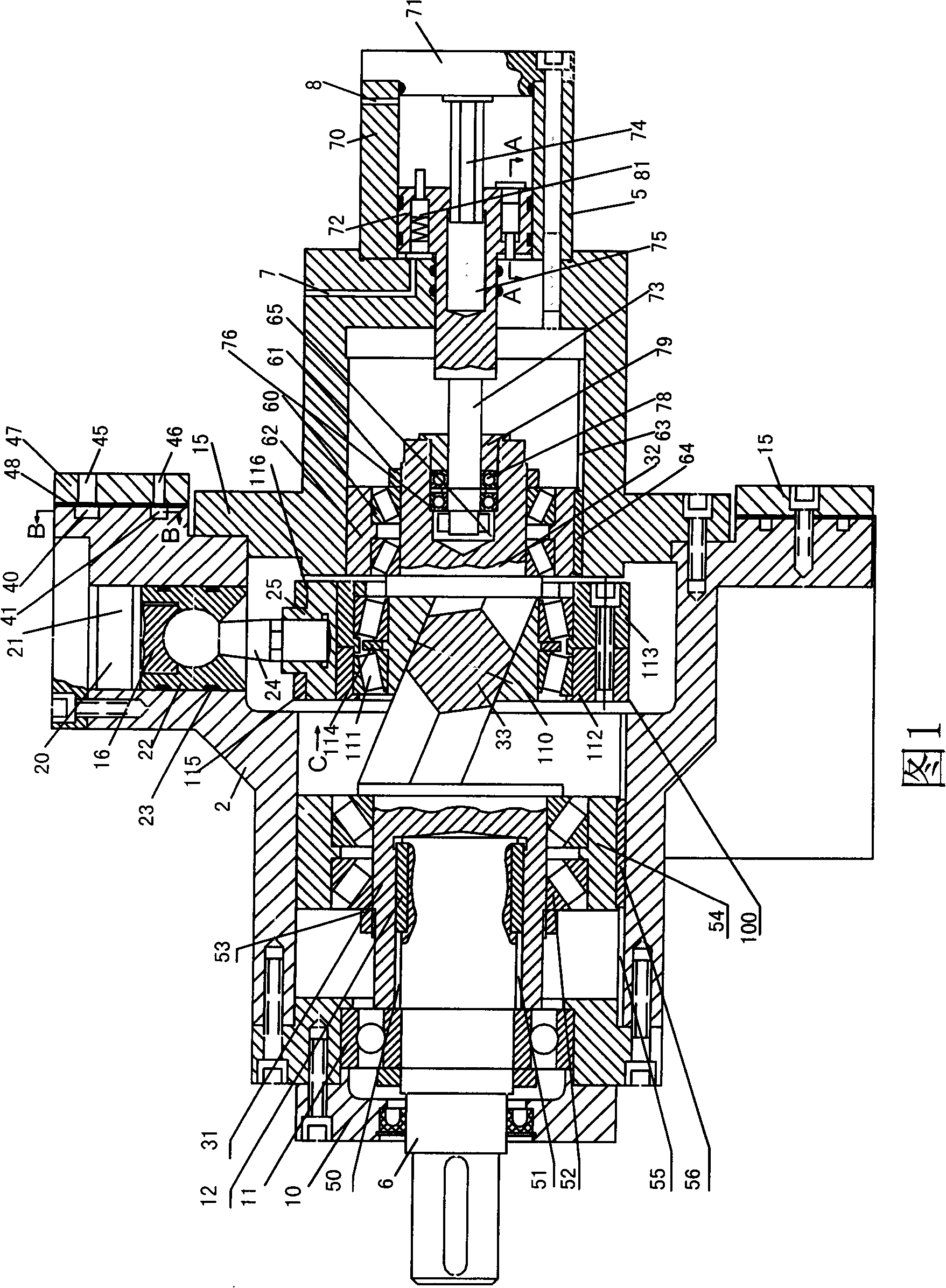
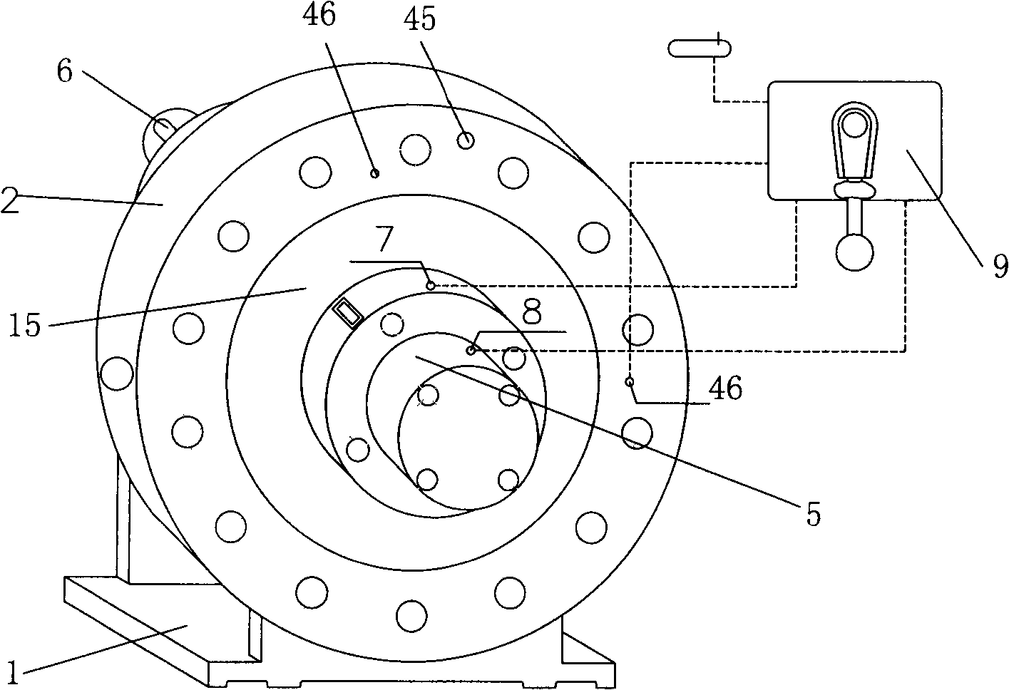
[0017] Such as figure 2 As shown, the shape of the oblique crankshaft variable displacement plunger pump includes a pump body 2 on the base 1, and an oil suction port 3 and an oil pressure port 4 on the pump body 2 for hydraulic oil to enter and exit. The pump body 2 is connected with the pump cover 15 , the variable adjusting device 5 is connected with the pump cover 15 in this embodiment, and the other end of the pump body 2 is connected with the transmission shaft 6 . The oil inlet hole 7 and the oil outlet hole 8 of the variable variable regulating device 5 can be connected with a variable variable control valve 9 .

[0018] The internal structure of the inclined crank variable displacement plunger pump is shown in Figure 1. The end face of the pump body 2 is connected ...


PUM


Abstract

The invention discloses a variable piston pump with an inclined crankshaft which includes a pump body; the end surfaces of the pump body are connected with the end covers; a transmission shaft penetrates the end covers of the pump body and are sealed with the end covers; piston devices are respectively arranged on the radical direction of the circle of the inner edge of the pump body; the incline crankshaft is arranged on the coaxial direction in the pump body; the incline crankshaft consists of at least three sections and is provided with a front section as well as a back section the axes of which are concentric; the crossed incline shaft section of the axes of the front section and the back section is arranged between the front section and the back section; the included angle of the axis of the incline shaft section and the front section as well as the back section is less than 25 degrees; wherein, one section of the incline crankshaft is a slide connection section and is connected with the transmission shaft in a sliding way; the other section of the incline crankshaft is a variable connection section and is connected with a variable adjusting device; the middle section of the incline crankshaft is the incline shaft section; a wobbler is arranged on the inclined shaft section; the circle of the wobbler is connected with the bottom part of the piston device. No flow distribution devices are arranged in the pump body of the variable piston pump with an incline crankshaft; simultaneously the pressure oil loss is reduced as no flow distribution devices are arranged; the variable range is large; the operation is convenient; rolling friction can be adopted on transmitting a main power, thus reducing a friction and improving the transmission efficiency. The invention relates to a completely novel hydraulic power device.

Description

technical field [0001] The invention belongs to hydraulic power components, in particular to a variable displacement plunger pump. Background technique [0002] At present, there are axial flow distribution devices in the structure of the radial variable plunger pump and the swash plate axial variable pump, such as CN200720031562.8, which consists of a housing, a pump cover, a flow distribution shaft, a drive shaft, a rotor, a stator, Composed of sliding shoes, limit valves and variable control valves, the internal distribution shaft, rotor, stator and other structures of this pump are relatively complex, and the pressure loss is relatively large. At the same time, the friction between the sliding shoes and the swash plate of the swash plate axial variable pump The loss is larger, that is, the friction loss of the main transmission is larger. Therefore, the maintenance and processing of the radial variable piston pump with axial flow distribution device is complicated and t...

Claims


Application Information

Patent Timeline
Patent Type & Authority Applications(China)
IPC IPC(8): F04B1/12F04B1/26F04B53/00
Inventor 谌文裕谌小堰
Owner 谌小堰
Why Eureka
Try Eureka