Eureka AIR delivers breakthrough ideas for toughest innovation challenges, trusted by R&D personnel around the world.

Anti-resonance vibrating sifter

An anti-resonance, vibrating screen technology, applied in the direction of filter screen, solid separation, grille, etc., can solve the problems of heavy machine weight, easy fatigue damage of screen box, high noise, etc., and achieve the effect of reducing motor power

Active Publication Date: 2009-02-04
NORTHEASTERN UNIV
View PDF0 Cites 20 Cited by
  • Summary
  • Abstract
  • Description
  • Claims
  • Application Information

AI Technical Summary

Problems solved by technology

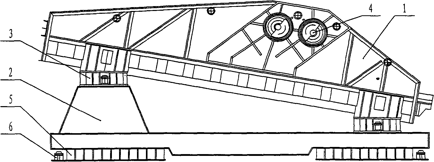
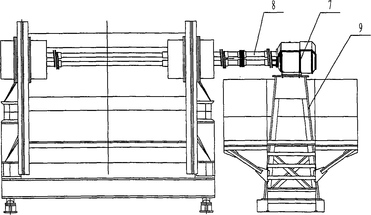
[0003] At present, most large-scale vibrating screens work far beyond the resonance state. They are large-scale non-resonant inertial vibrating screens. Their structures are as follows: figure 1 It can be seen from the figure that the large-scale non-resonant inertial vibrating screen consists of the following parts: 1 screen box (upper plastid), 2 secondary vibration isolation frame (lower plastid), 3 primary vibration isolation spring, 4. Exciter, 5. Secondary vibration isolation spring, 6. Buffer, 7. Motor, 8. Transmission shaft, 9. Motor support. The disadvantage is that the traditional vibrating screen, regardless of resonance or non-resonance, is installed on the upper plastid Above, the surrounding of the vibrator needs to be reinforced, the mass of the vibration is large, and the screen box is directly affected by the exciting force, so the screen box is easy to be fatigued and damaged, the noise is large, and the vibration isolation effect is poor. For non-resonant screens, in order to improve vibration isolation As a result, the screen box must be placed on a secondary vibration isolation frame, the weight of the whole machine is relatively large, the failure rate of the screen box is high, and the service life is not ideal

Method used


Image

  • Anti-resonance vibrating sifter
  • Anti-resonance vibrating sifter
  • Anti-resonance vibrating sifter

Examples


Embodiment Construction

[0061] The detailed structure of the present invention is described in conjunction with the following examples and accompanying drawings.

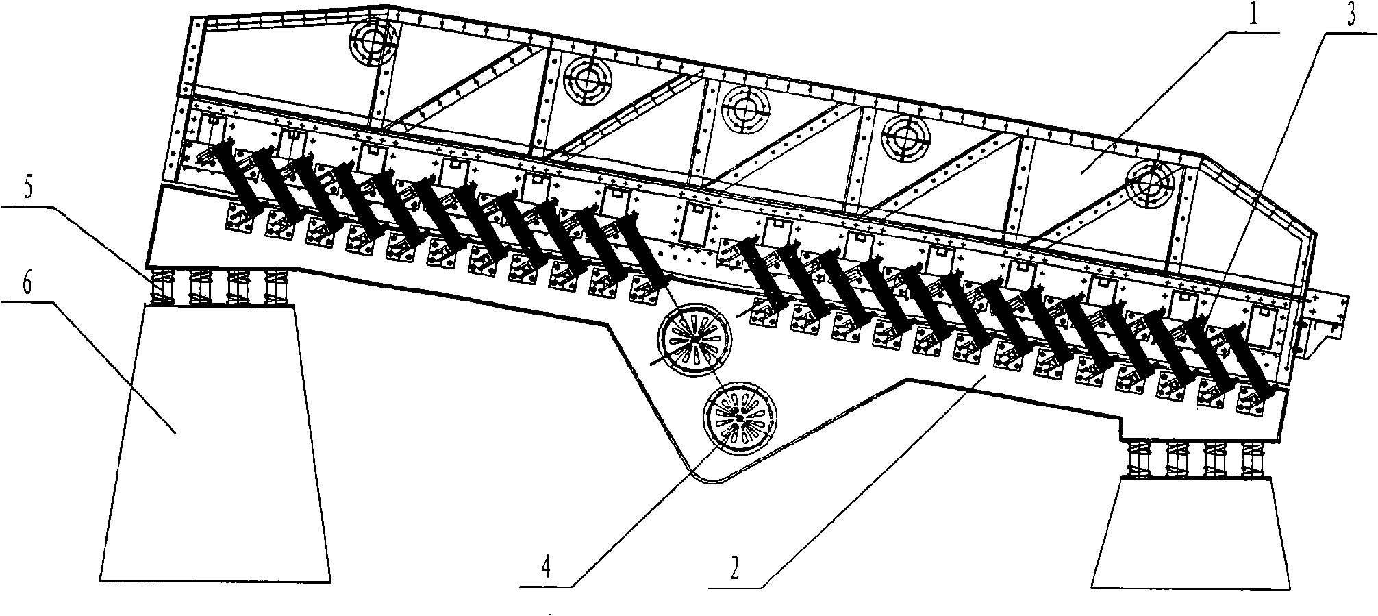
[0062] The structure of the present invention is as image 3 As shown, the upper plastid of the screen box (1) is the working part of the anti-resonance vibrating screen, the lower plastid of the exciter (2) is the driving part, and the exciter (4) is installed on the exciter (2). The screen box (1) and the vibrating body (2) are connected through the main vibration spring (3), the vibrating body (2) is seated on the foundation (6) through the vibration isolation spring (5), and the motor (7) is installed on the on the motor bracket (9), and connected to the exciter (4) through the transmission shaft (8); the main vibration spring in this embodiment is a leaf spring, which is divided into multiple groups, each group has multiple pieces, and the total stiffness of the main vibration spring is easy to adjust. Mass ratio of upper and lower p...


PUM


Abstract

The present invention relates to an anti-resonance vibration sieve, which belongs to the technical field of vibration machinery. The anti-resonance vibration sieve comprises a sieve box as an upper plasmid, an excitation body as a lower plasmid, a master vibration spring, a vibration generator, an isolation spring, a base, a motor, etc. The sieve box upper plasmid is a working part of the anti-resonance vibration sieve, and the excitation body lower plasmid is a driving part. The excitation body is equipped with the vibration generator. The sieve box and the excitation body are connected by the master vibration spring. The excitation body is located on the base by the isolation spring. The motor is arranged at a motor frame and is connected with the vibration generator by a transmission shaft. The anti-resonance vibration sieve has the advantages that the sieve box of the anti-resonance vibration sieve is provided with the vibration generator, the mass of vibration can be totally reduced by 20 percent to 30 percent, so that the excitation force is reduced, and the motor power is also reduced, thereby being good for saving energy; the master vibration spring is distributed along the direction of a lateral board of the sieve box, and the sieve box bears force uniformly, thereby being good for prolonging the service life of the sieve; the vibration generator is arranged at the lower plasmid, the lower plasmid almost does not vibrate, and the requirement on rigidity and strength can be ensured easily. The noise of the whole machine is reduced obviously.

Description

technical field [0001] The invention relates to the technical field of vibrating machinery, which is suitable for the classification of raw coal, minerals, sintered ore and other various bulk materials. Background technique [0002] Vibrating machinery is a large class of mechanical equipment that uses vibration to complete various processes, such as vibrating conveyors, vibrating screens, vibrating dryers, vibrating road rollers, etc. There are many types of traditional vibrating screens, and there are coal grading vibrating screens according to their uses. , ore grading vibrating screen, cold ore sieve, hot ore sieve, etc.; according to the screening principle, there are probability sieve, equal thickness sieve, probability equal thickness sieve, etc.; according to the driving principle, there are elastic connecting rod type, electromagnetic type, inertial type , pneumatic and hydraulic methods; it can also be divided according to dynamic characteristics, such as whether t...

Claims


Application Information

Patent Timeline
IPC IPC(8): B07B1/28B07B1/42
Inventor 刘杰刘劲涛李允公戴丽
Owner NORTHEASTERN UNIV
Why Eureka
Eureka Blog
Learn More