
Active element array substrate

A technology of array substrates and active components, applied in the field of active component array substrates, can solve problems such as the decline of protection capabilities, and achieve the effect of reducing mutual interference

Inactive Publication Date: 2009-01-21
CHUNGHWA PICTURE TUBES LTD
View PDF0 Cites 9 Cited by
  • Summary
  • Abstract
  • Description
  • Claims
  • Application Information

AI Technical Summary

Problems solved by technology

However, the protection ability of the thin film transistor array substrate against electrostatic discharge is reduced after removing the external electrostatic discharge protection ring.

Method used


Image

  • Active element array substrate
  • Active element array substrate
  • Active element array substrate

Examples


no. 1 example

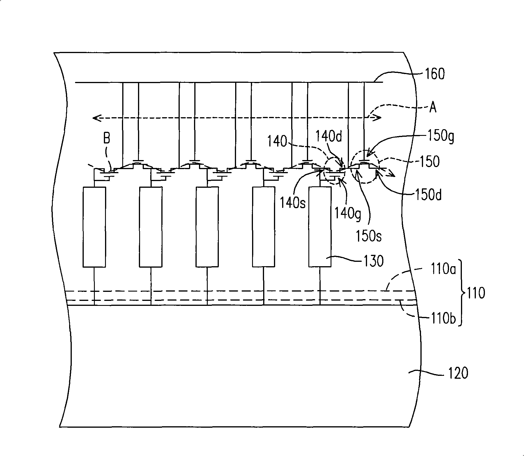
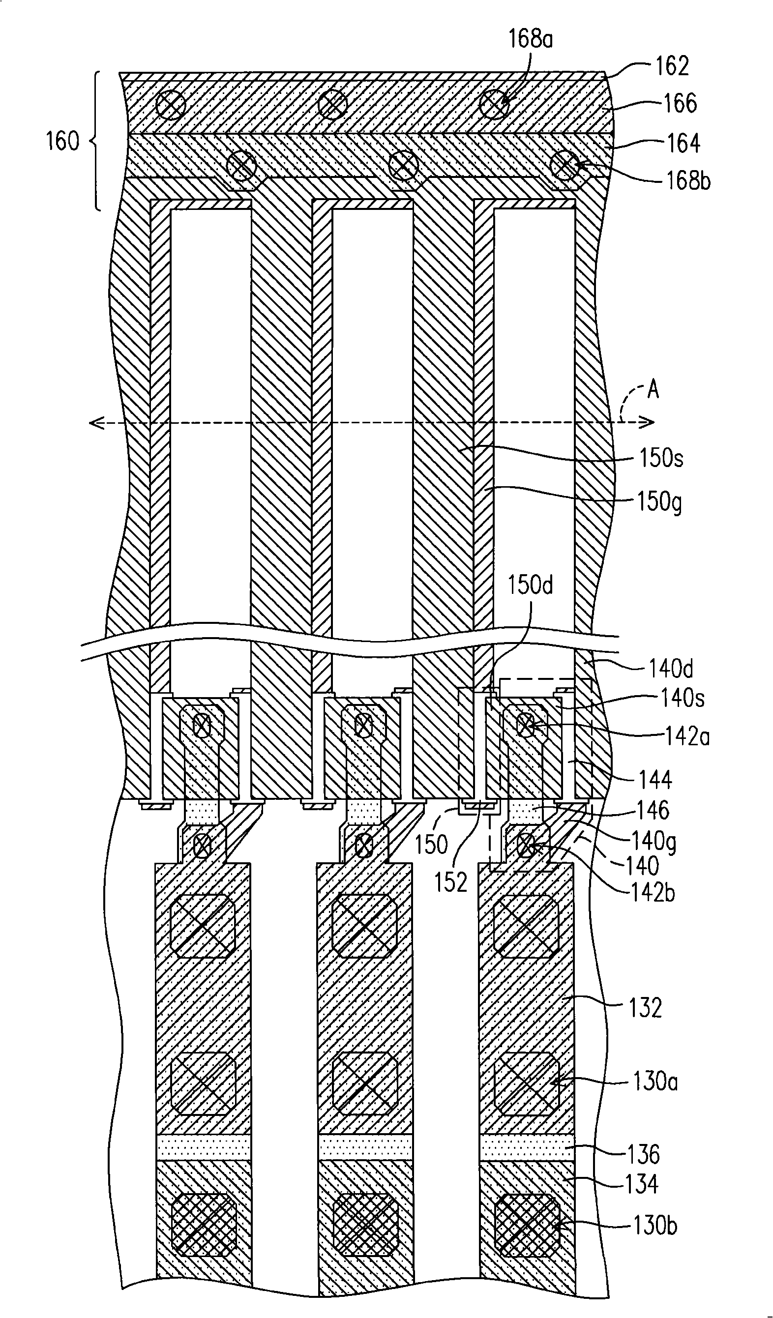
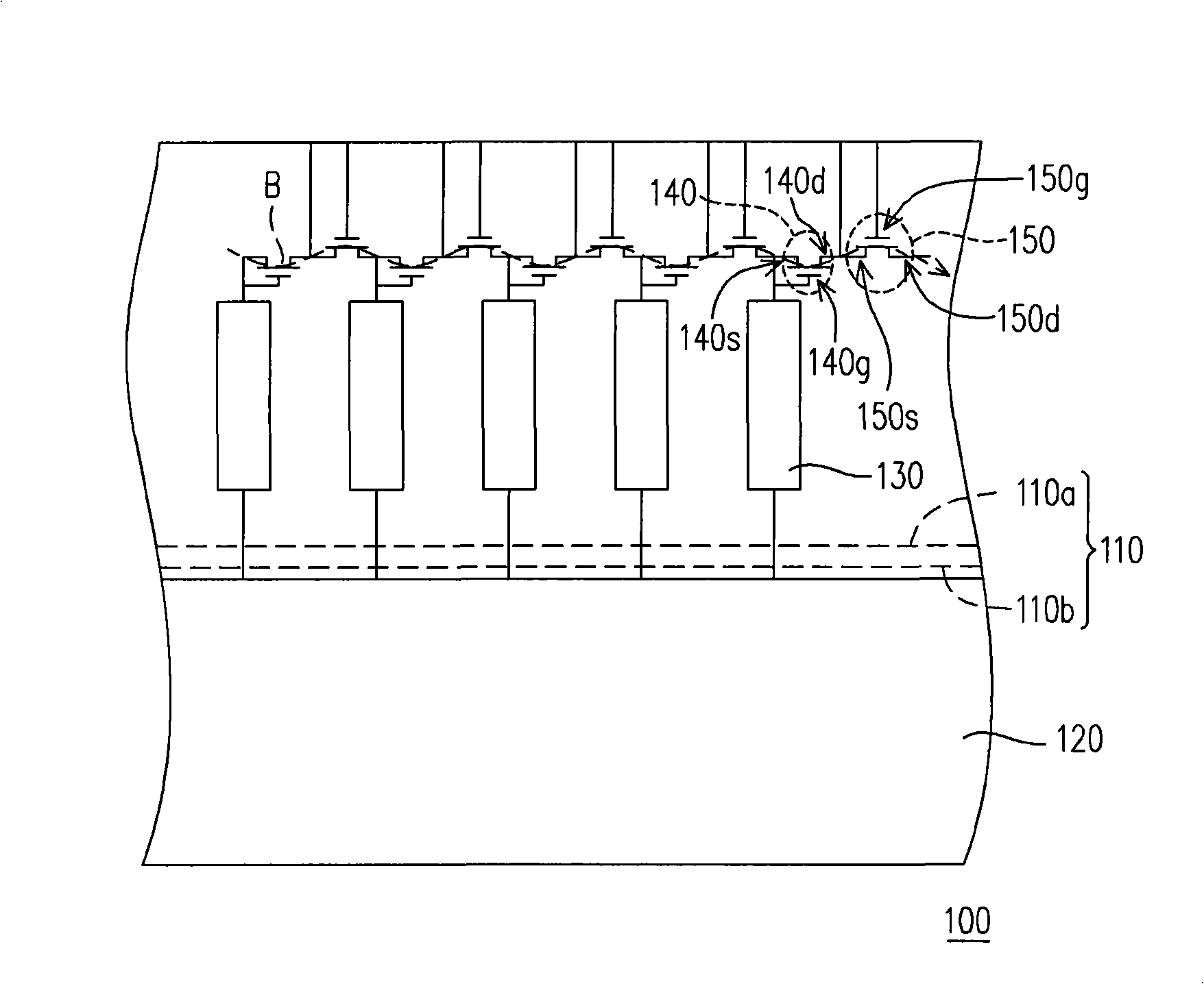
[0040] Figure 1A It is an equivalent circuit diagram of an active device array substrate before cutting process according to the first embodiment of the present invention. Figure 1B It is a top view of an active device array substrate before the cutting process according to the first embodiment of the present invention, and the pixel array is not shown.

[0041] Please refer to Figure 1A In this embodiment, the method for manufacturing an active device array substrate includes the following steps. Firstly, a substrate 110 is provided, and the substrate 110 has a peripheral circuit area 110a and a display area 110b, wherein a pixel array 120 has been formed on the display area 110b. The pixel array 120 generally includes a plurality of scan lines, a plurality of data lines, a plurality of thin film transistors, and a plurality of pixel electrodes, but for the sake of simplicity, the detailed structure of the pixel array 120 is not shown. In addition, a plurality of pads 130...

no. 2 example

[0051] Figure 3A It is an equivalent circuit diagram of an active device array substrate before cutting process according to the second embodiment of the present invention. Figure 3B It is a top view of an active device array substrate before the cutting process according to the second embodiment of the present invention, and the pixel array is not shown. Please refer to Figure 3A , this embodiment is similar to the first embodiment, the difference is that: the gate 250g of each second switching element 250 is electrically connected to the source 250s. Therefore, the second switching element 250 can be regarded as a diode. In addition, the drain 250d of the second switching element 250 is electrically connected to the source 140s of the first switching element 140 .

[0052] The detailed structure will be described in detail below, but it is worth noting that, Figure 3A The structure represented by the equivalent circuit diagram is not limited to Figure 3B The struct...

no. 3 example

[0057] Figure 5A It is an equivalent circuit diagram of an active device array substrate before cutting process according to the third embodiment of the present invention. Figure 5B It is a top view of an active device array substrate before the cutting process according to the third embodiment of the present invention, and the pixel array is not shown. Please refer to Figure 5A , this embodiment is similar to the first embodiment, the difference is that: a connection line 370 is also formed on the peripheral circuit area 110a of the substrate 110, which is arranged outside the first switching element 140 and the second switching element 150, And the source 150s of each second switching element 150 is electrically connected to the connection line 370 .

[0058] The detailed structure will be described in detail below, but it is worth noting that, Figure 5A The structure represented by the equivalent circuit diagram is not limited to Figure 5B The structure shown. Tho...


PUM


Abstract

The invention relates to a driving element array base-plate, which comprises a base-plate, a pixel array, a plurality of jointing pads, a plurality of first and second switch elements, wherein the pixel array is arranged on a display area of the base-plate, the jointing pads and the first and the second switch elements are all arranged on the peripheral circuit areas of the base-plate, and the jointing pads are electrically connected with the pixel array. Both of the first and the second switch elements are positioned on the outer sides of the jointing pads, and each of the first switch elements is respectively and electrically connected with one of the jointing pads, each of the first switch element is provided with a grid electrode, a source electrode and a drain, wherein the grid electrode is respectively and electrically connected to the source electrode and the jointing pads, each of the second switch elements is respectively and electrically connected to two of the first switch elements which are adjacent, and each of the second switch elements is provided with the grid electrode, the source electrode and the drain, and the source electrode is electrically connected with the drain of the first switch element which is adjacent with the source electrode, and the drain is electrically connected with the source electrode of the first switch element which is adjacent with the drain. The driving element array base-plate adopts the first switch elements and the second switch elements to electrically connect each of the jointing pads, thereby the base-plate has the electrostatic discharge protection function.

Description

technical field [0001] The present invention relates to an array substrate, and in particular to an active element array substrate. Background technique [0002] Due to the increasing demand for displays, the industry is fully committed to the development of related displays. Among them, the cathode ray tube (cathode ray tube, CRT) has been monopolizing the display market for many years because of its excellent display quality and technological maturity. However, due to the rise of the concept of green environmental protection, the characteristics of large energy consumption and large radiation, and the limited space for product flattening, it cannot meet the market demand for light, thin, short, small, beautiful and low power consumption. market trends. Therefore, a thin film transistor liquid crystal display (TFT-LCD) with superior characteristics such as high image quality, good space utilization efficiency, low power consumption, and no radiation has gradually become t...

Claims


Application Information

Patent Timeline
Patent Type & Authority Applications(China)
IPC IPC(8): H01L27/12H01L23/522H01L23/60G02F1/1362
Inventor 刘文雄何建国
Owner CHUNGHWA PICTURE TUBES LTD
Learn More