Radiating fin and fin component

A technology of heat dissipation fins and components, which is applied to parts of instruments, cooling of instruments, instruments, etc., can solve the problems of low heat absorption efficiency and achieve high heat absorption efficiency and simple structure of heat dissipation fins

Inactive Publication Date: 2009-01-21
MITAC PRECISION TECH(KUNSHAN) CORP
View PDF0 Cites 3 Cited by
  • Summary
  • Abstract
  • Description
  • Claims
  • Application Information

AI Technical Summary

Problems solved by technology

[0003] However, the current heat dissipation fin assembly is a single-layer substrate structure, and the heat absorption efficiency is low

Method used


Image

  • Radiating fin and fin component
  • Radiating fin and fin component
  • Radiating fin and fin component

Examples


Embodiment Construction

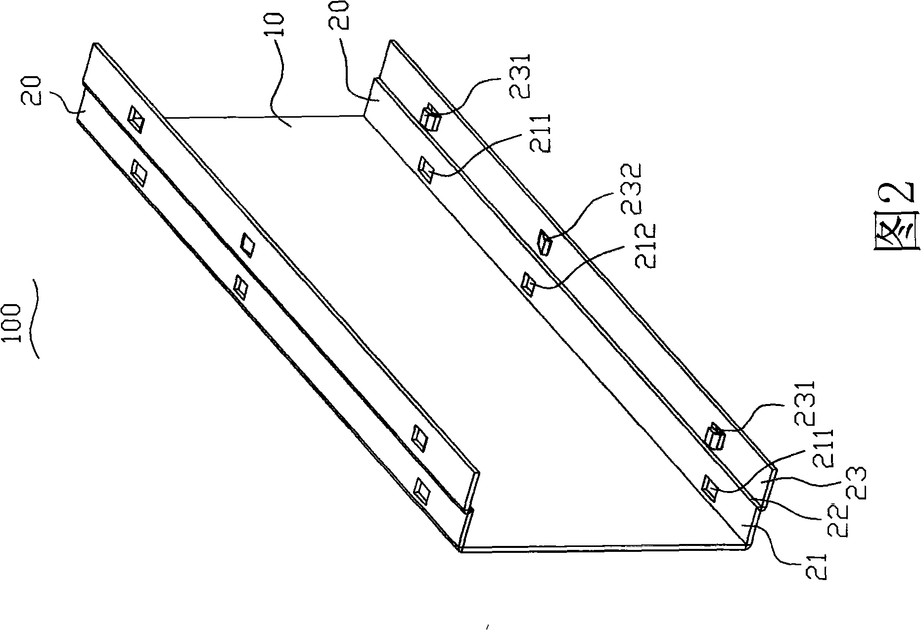
[0016] Please refer to Figure 2 and image 3 As shown, the first embodiment provides a heat dissipation fin 100 with a symmetrical structure (the heat dissipation fin 100 can also be arranged in an asymmetric structure), and the heat dissipation fin 100 includes a body 10; two sides of the body 10 A buckling portion 20 is symmetrically provided, and the buckling portion 20 includes a first bent portion 21, one side of the first bent portion 21 is vertically arranged on one side of the body 10, and the first bent portion 21 is provided with There are two clamping holes 211 (the number of clamping holes 211 is determined according to actual needs, which can be 1, 2 or more) and a limit hole 212 (the number of limit holes 212 is determined according to actual needs, which can be 1 or 2 or more), in this embodiment, the clamping hole 211 and the limiting hole 212 are arranged on the same straight line; and the other side of the first bending portion 21 is vertically provided with o...


PUM


Abstract

The invention provides a heat dissipation fin and a fin component, wherein the heat dissipation fin comprises a body, one side of the body is equipped with a holding portion, the holding portion comprises a first bending portion, one side of the bending portion is vertically arranged on one side of the body, and a card hole and a limit hole are arranged on the first bending portion. The other side of the first bending portion is vertically arranged on one side of a second bending portion, the other side of the second bending portion is equipped with a third bending portion, and a hook and a limit portion which are inwardly bulgy are arranged. The fin component comprises a plurality of heat dissipation fins which are stacked, wherein the first bending portion of a next heat dissipation fin is arranged in the third bending portion of a former one heat dissipation fin, the limit holes of the next heat dissipation fin respectively contains the limit portion of the former one heat dissipation fin, and the card holes of the next heat dissipation fin respectively catch the hook of the former one heat dissipation fin. The heat dissipation fin has simple structure, and the heat dissipation fins are arranged and combined into a fin component, which is very convenient and does not need any mechanical equipment.

Description

【Technical field】 [0001] The invention relates to a heat dissipation fin and a fin assembly, in particular to a heat dissipation fin and a fin assembly with high heat absorption efficiency. 【Background technique】 [0002] Heat dissipation fins and fin components are widely used in the field of heat sinks. Please refer to FIG. A heat dissipation fin 30' is disposed between the first substrate 10' and the second substrate 20'. Combine several cooling fins to form a fin assembly. The heat dissipation principle of the fin assembly is: the first substrate 10' is in contact with the second substrate 20' and the heat source to absorb the heat generated by the heat source, and then dissipate the absorbed heat. The heat is transferred to the heat dissipation fins 30', so that the absorbed heat is transferred to fluids such as air through these heat dissipation fins 30', so as to achieve the purpose of heat dissipation. [0003] However, the heat dissipation fin assembly currently h...

Claims


Application Information

Patent Timeline
Patent Type & Authority Applications(China)
IPC IPC(8): G12B15/06
Inventor 余春杨
Owner MITAC PRECISION TECH(KUNSHAN) CORP
Why Eureka
Try Eureka