Underground continuous wall construction method crossing city pipelines

A technology of underground diaphragm wall and construction method, applied in sheet pile wall, infrastructure engineering, construction and other directions, can solve the problems of difficulty in hoisting the steel cage, affect the stability, inaccuracy, etc., to avoid pipeline relocation, anti-leakage, etc. The effect of strong ability and stability improvement

Inactive Publication Date: 2009-01-21
SHANGHAI CONSTRUCTION GROUP
View PDF0 Cites 11 Cited by
  • Summary
  • Abstract
  • Description
  • Claims
  • Application Information

AI Technical Summary

Problems solved by technology

Although the closure of the underground diaphragm wall 110 structure can be ensured, the resulting pipeline cutting and modification takes too long and costs a lot, and the problem of pipeline cutting and modification often occurs and affects the progress of the project, resulting in a sharp increase in the overall cost of the project construction
[0004] If in-situ protection measures are taken for the pipeline, the current conventional technology cannot guarantee the sealing of the underground diaphragm wall structure, and the sealing performance of the underground diaphragm wall structure will directly affect the stability of the foundation pit. The difficulty of sealing the underground diaphragm wall lies in the reinforcement cage under the pipeline. Hanging, the existing method has the method of obliquely placing the reinforcement cage (such as figure 2 As shown), first place the lock pipe 210 obliquely, then put the steel cage 220 obliquely along the lock pipe 210 into the groove, and make the steel cage part fall below the underground pipeline 230 by lifting, and finally pour concrete to complete the underground continuous wall
[0005] However, this method has many shortcomings: in actual construction, the steel cage cannot be completely attached to the lock pipe, and the lateral guidance of the steel cage is difficult to control and is not accurate enough, which finally makes the steel cage difficult to hang; If the storage time is too long, the tank wall will be exposed for a long time, which will affect its stability; the depth of the underground diaphragm wall will be limited

Method used


Image

  • Underground continuous wall construction method crossing city pipelines
  • Underground continuous wall construction method crossing city pipelines
  • Underground continuous wall construction method crossing city pipelines

Examples


Embodiment Construction

[0016] In order to make the purpose and features of the present invention more obvious and understandable, the present invention will be further described by giving preferred embodiments and in conjunction with the accompanying drawings.

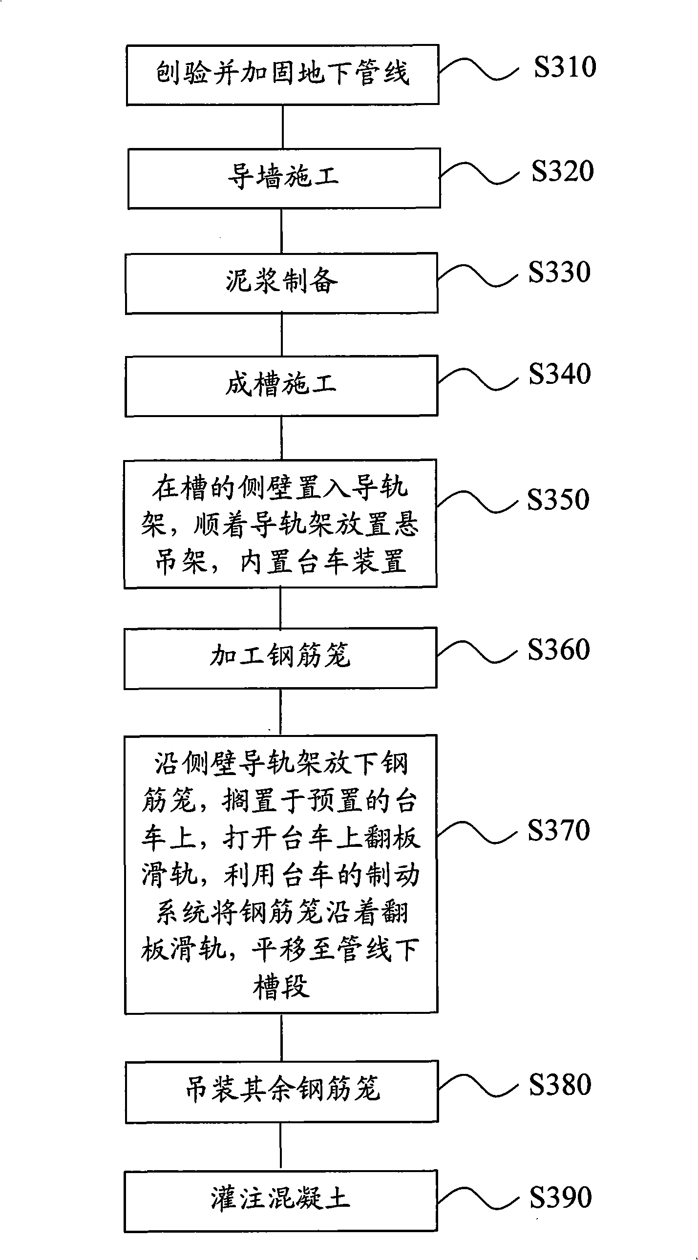
[0017] See image 3 It is a flow chart of the construction method provided by an embodiment of the present invention.

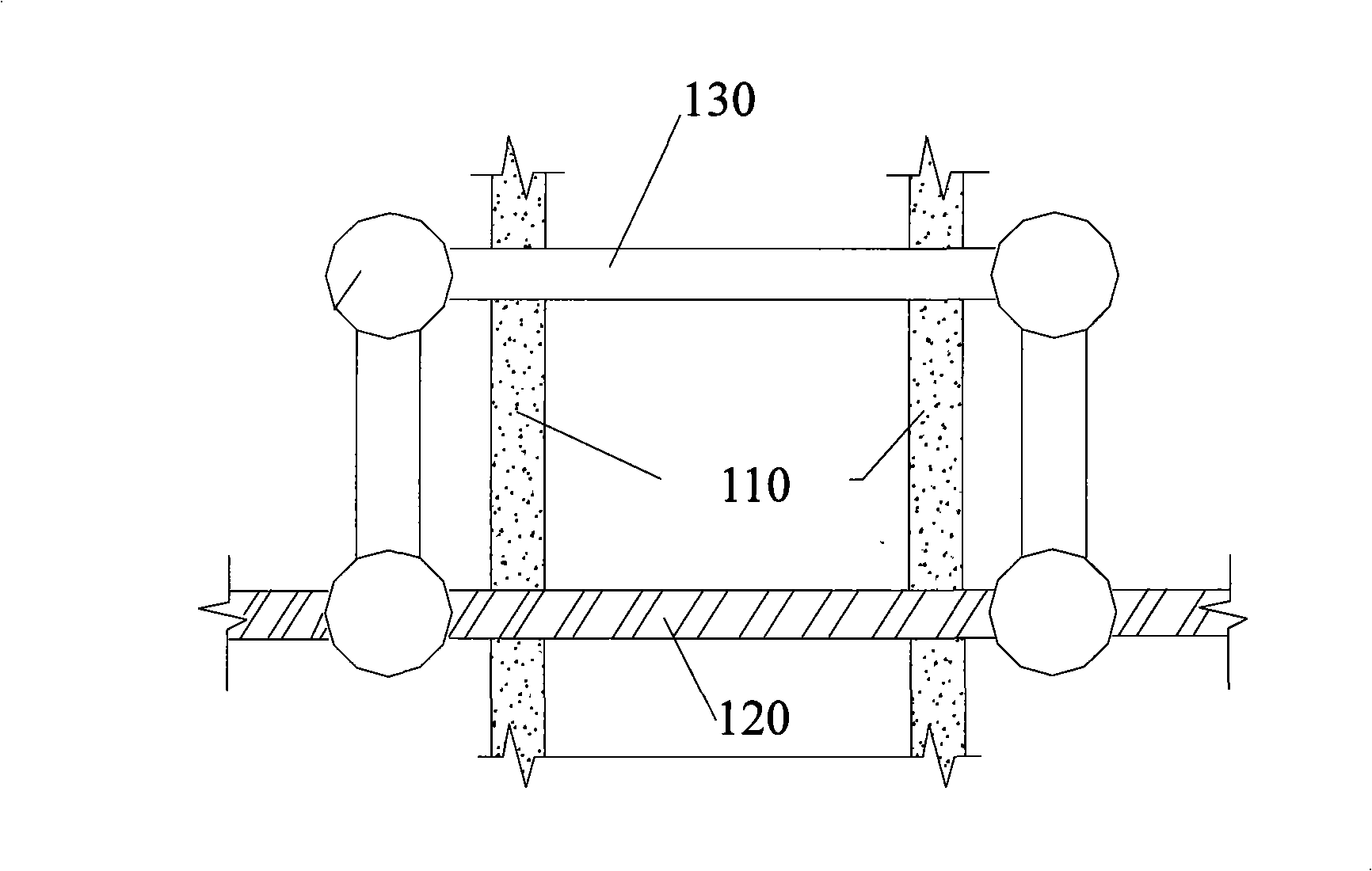
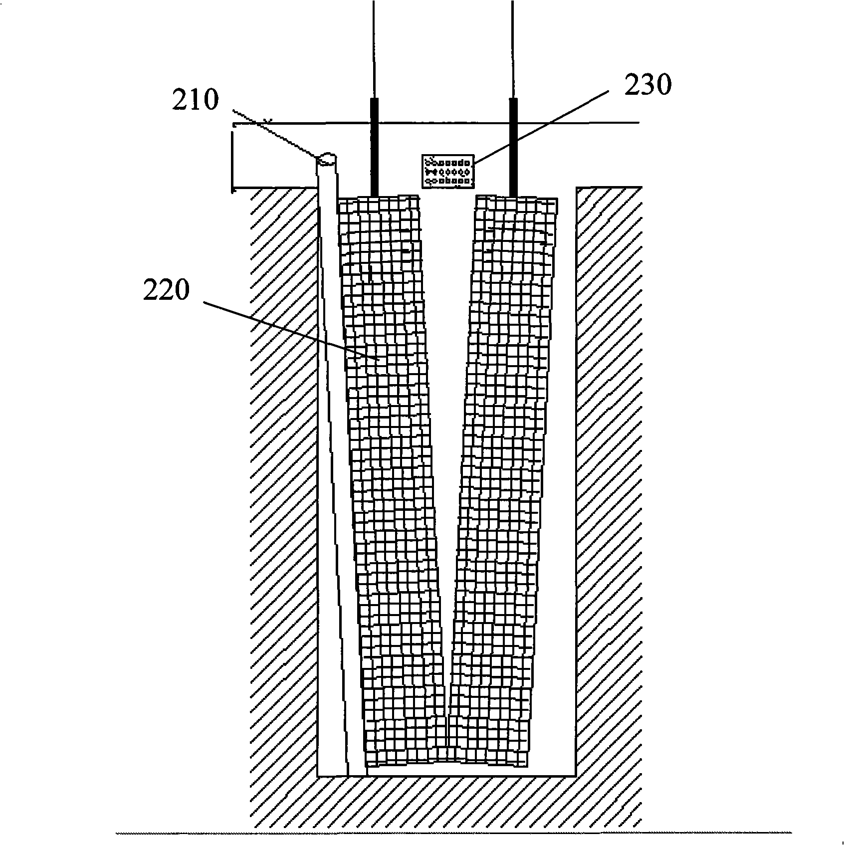
[0018] Step S310: Examine and strengthen the underground pipelines. Where there are pipelines, steel pipes or section steel can be added to reinforce and protect the pipelines at a place 50cm below the pipelines. It will not be damaged during construction.

[0019] Step S320: guide wall construction. When excavating the guide wall, in order to facilitate the protection of underground pipelines and adjust the position of the steel cage after lowering, the width of the guide wall should be increased appropriately. For example, when excavating a deep groove with a width of 120cm and a depth of 120-200cm, the depth should be ...


PUM


Abstract

The invention provides a method for constructing an underground continuous wall traversing an urban pipeline; and the method is utilize to make the underground continuous wall have good integrality, high verticality, good anti-seepage performance and small influence on ambient environment, thereby well protecting underground buildings. The construction method comprises the following steps: a pipeline is planed, tested and reinforced; the guide wall is constructed; slurry is prepared; a groove is formed and constructed; after groove forming is completed, a guide rail rack is positioned in one sidewall of the groove; a suspension rack is positioned along the guide rail rack, wherein the suspension rack is provided with a trolley device inside; a trolley is provided with a braking system and a slide rail for a turned plate; a steelwork cage is processed, put down along the guide rail rack and positioned on the trolley; the slide rail of the turned plate is opened; the braking system of the trolley is utilized to translate the steelwork cage to the lower groove section of the pipeline along the slide rail of the turned plate; and the other steelwork cages are lifted and filled with concrete.

Description

technical field [0001] The invention relates to a construction method of an underground diaphragm wall, in particular to a construction method of an underground diaphragm wall spanning urban pipelines. Background technique [0002] Underground space development projects in modern cities are often difficult to construct due to the complex distribution of underground pipelines. Underground obstacles such as crossing urban pipelines have a greater impact on the foundation pit enclosure structure for underground space development. [0003] For example, the commonly used construction methods in urban subway construction include open-cut method, cover-excavation method and mixed construction method. Most of the urban pipelines within the construction scope adopt the method of secondary cutting and modification (such as figure 1 As shown), before the construction, the original underground pipeline 120 that crosses the underground connection wall 110 in the construction scope is c...

Claims


Application Information

Patent Timeline
Patent Type & Authority Applications(China)
IPC IPC(8): E02D5/18
Inventor 吴小建陈峰军许抒
Owner SHANGHAI CONSTRUCTION GROUP
Why Eureka
Try Eureka