
Continuous media web heater

A technology for heating controllers and media, applied to instruments, equipment for electrical recording processes using charge patterns, printing, etc., can solve problems such as smearing or offset, scraping or peeling, ink not curing, etc.

Inactive Publication Date: 2009-01-21
XEROX CORP
View PDF0 Cites 6 Cited by
  • Summary
  • Abstract
  • Description
  • Claims
  • Application Information

AI Technical Summary

Problems solved by technology

Such small ink droplets or images may have poor adhesion or may be easily scratched or peeled off by folding or bending actions, or may be subject to smearing or offset to other sheets
If the media is heated to an excessively high temperature, the size of the ink dots and drops will vary depending on the characteristics of the media, and in some cases the ink may not solidify before completely penetrating the paper, resulting in what is known as "show-through." "Defective condition of

Method used


Image

  • Continuous media web heater
  • Continuous media web heater
  • Continuous media web heater

Examples


Embodiment Construction

[0020] For a general understanding of the present embodiment, reference is made to the accompanying drawings. In the drawings, like reference numerals are used to designate like elements throughout the figures.

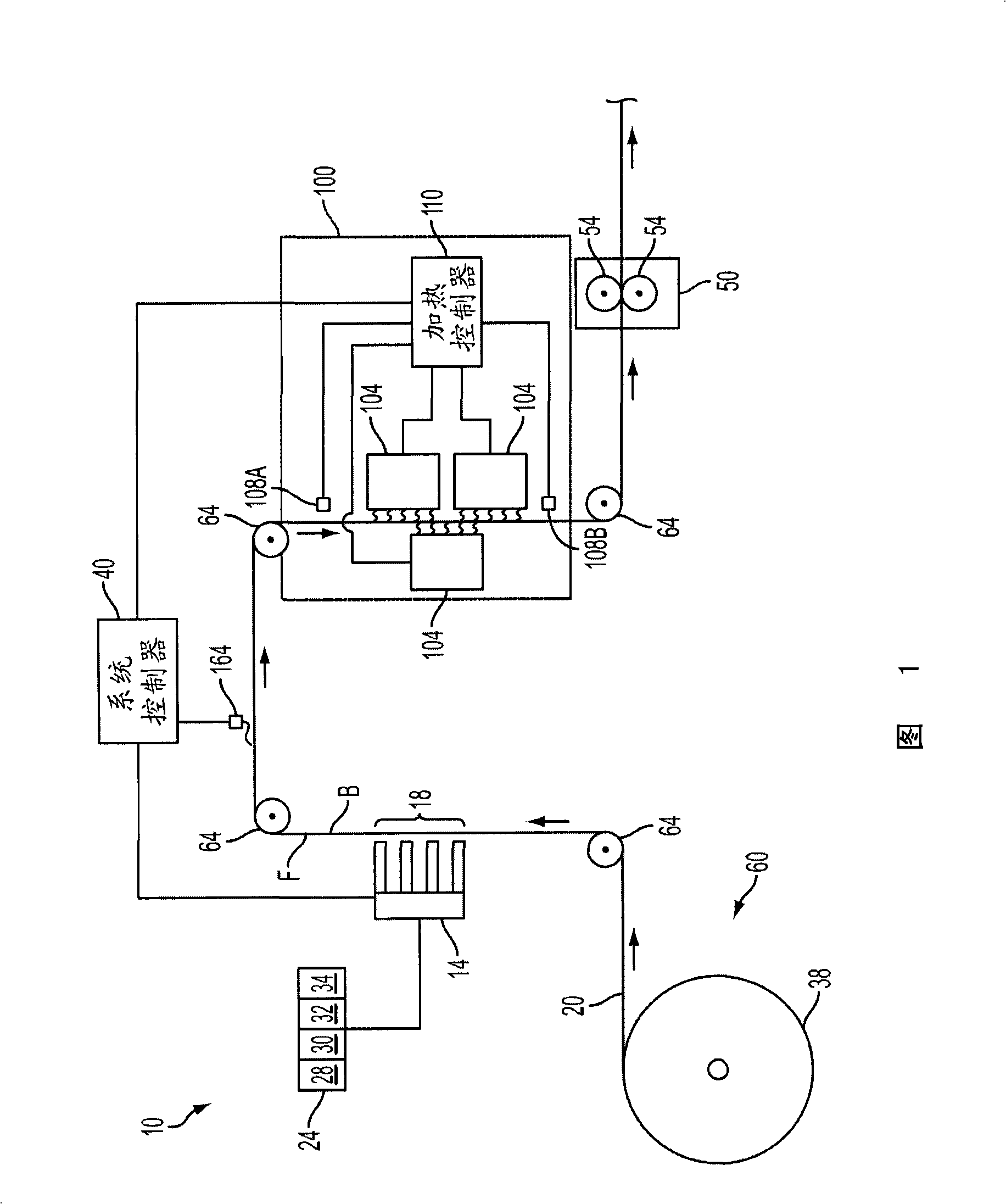
[0021] Figure 1 schematically illustrates an imaging device 10, or at least a portion of an imaging device 10, showing elements relevant to the present disclosure. In the illustrated embodiment, imaging device 10 implements a solid ink printing process to print on a continuous web of media. To this end, imaging apparatus 10 includes a web supply and handling system, a phase change ink printing system, and a web heating system. Although the web heating system is described as being used in a phase change ink imaging device, the web heating system can be used in any of a variety of other imaging devices including, for example, laser printers, facsimile machines, copiers or capable of applying one or more colorants Any other imaging device applied to a continuous web of...


PUM


Abstract

The present invention relates to a continuous medium pair heater. A radiant heating device comprises a housing having an opening for positioning adjacent a media web in an imaging device. A pair of radiant heating panels is positionable in the housing to any one of a plurality of positions between and including a fully open position in which the pair of radiant heating panels are positioned side by side in the opening of the housing and facing the media web and a retracted position in which the pair of radiant heating panels are inside the housing and facing each other. The radiant panels are configured to emit thermal radiation in accordance with a variable thermal output signal. A panel driver is operably coupled to the pair of radiant heating panels for positioning the pair of radiant heating panels to at least one of the plurality of positions in response to a variable view factor signal.

Description

technical field [0001] The present disclosure relates generally to imaging devices that generate images on a continuous web of media, and more particularly to heaters for thermally conditioning the continuous web of media prior to securing the images to the web. Background technique [0002] Generally, an inkjet printing machine or printer includes at least one printhead unit that discharges droplets or jets of liquid ink onto a recording or image forming medium. Phase Change Inkjet printers utilize phase change inks that are in a solid phase at ambient temperatures but transition to a liquid phase at elevated temperatures. The molten ink can then be ejected as ink droplets or jets onto the print medium at the elevated operating temperature of the machine or printer by the mounted printhead unit. The ink can be discharged directly onto the image receiving substrate, or indirectly onto an intermediate imaging member before the image is transferred to the image receiving subs...

Claims


Application Information

Patent Timeline
IPC IPC(8): B41J2/01B41J11/00B41J15/00G03G15/20
CPCB41J11/002B41J11/00216B41J2/315B41J2/435
Inventor R·莱顿P·J·麦康维尔V·M·威廉斯
Owner XEROX CORP
Learn More