Comparator and A/D converter
A technology of comparators and comparison results, applied in analog/digital conversion, code conversion, instruments, etc., to achieve the effects of expanding frequency, improving comparison accuracy, and overcoming offset
- Summary
- Abstract
- Description
- Claims
- Application Information
AI Technical Summary
Problems solved by technology
Method used
Image
Examples
Embodiment approach 1
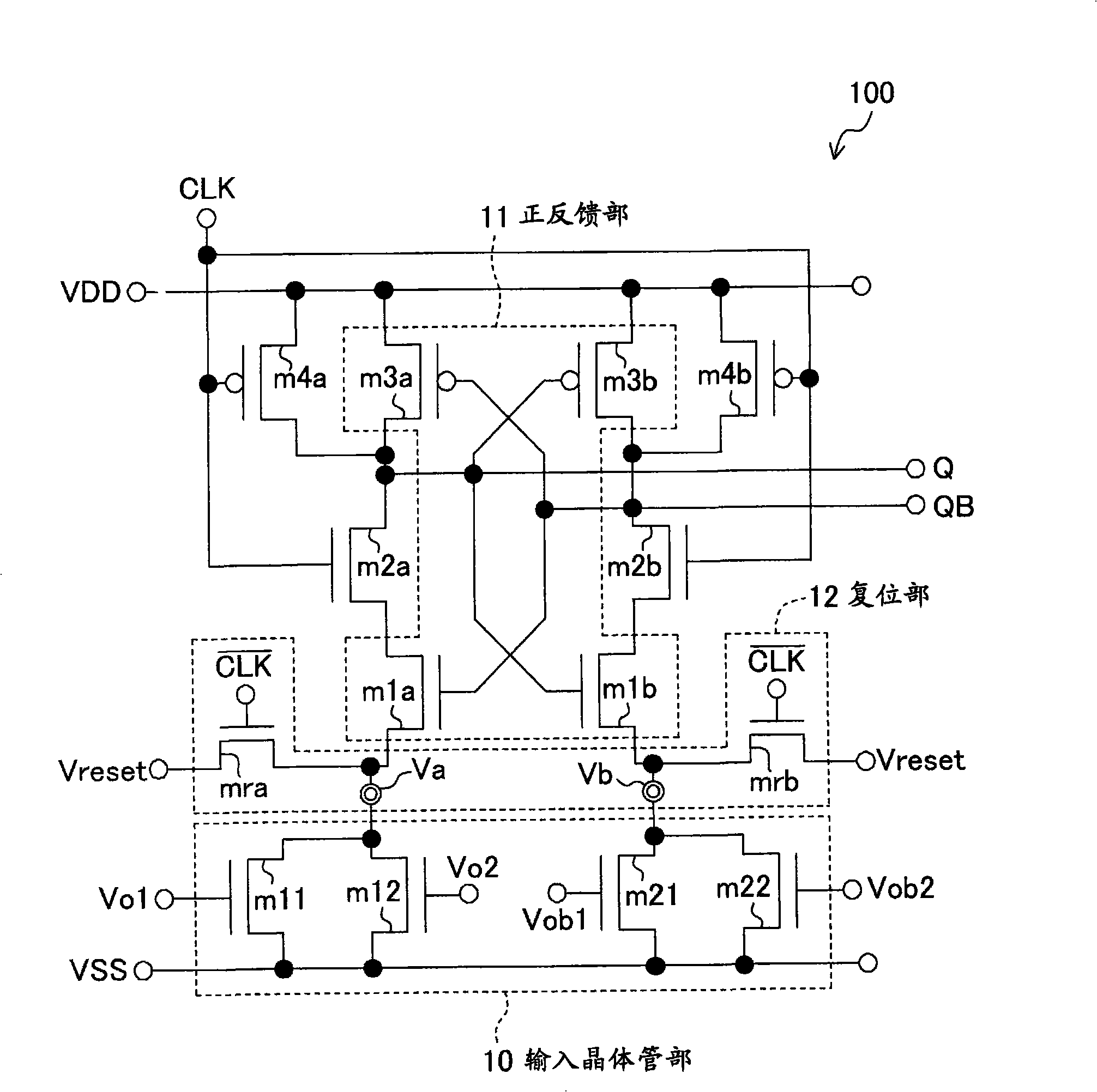
[0075] figure 1 It is a figure which shows an example of the structure of the dynamic comparator 100 of this Embodiment 1.
[0076] exist figure 1 Among them, the comparator 100 includes: an input transistor part 10 including NMOS transistors m11, m12, m21, m22, a positive feedback part (cross-coupled inverting latch part) 11 including NMOS transistors m1a, m1b and PMOS transistors m3a, m3b, The output terminal QB is connected to the gate terminals of m1a and m3a of the positive feedback part 11 and the drain terminal of m3b, and the gate terminals of the transistors m1b and m3b of the positive feedback part 11 are connected to the drain terminal of the transistor m3a. Output terminal Q.
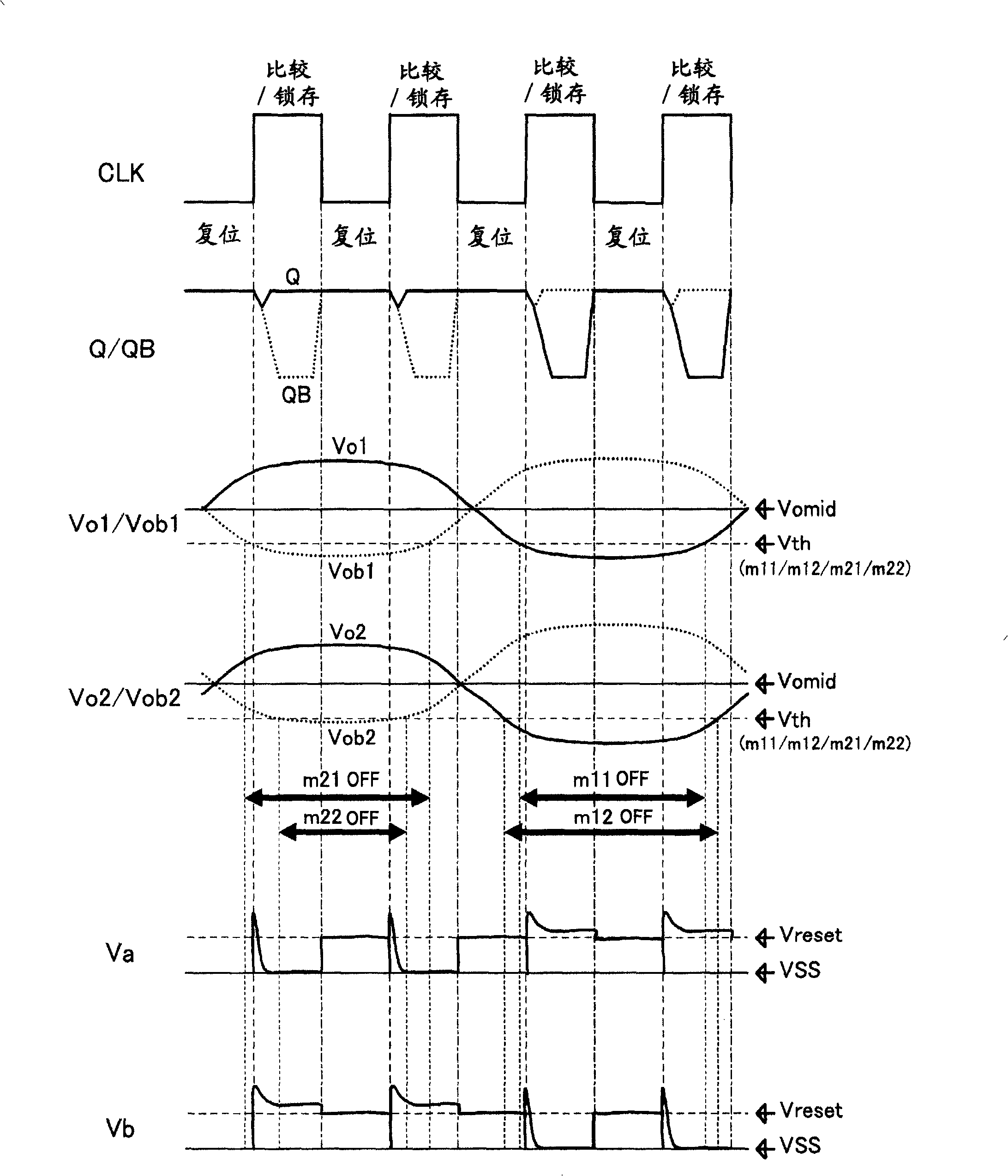
[0077] In addition, in figure 1 In, between the drain terminal of the NMOS transistor m1a and the drain terminal of the PMOS transistor m3a is connected the NMOS transistor m2a which is synchronized with the clock signal CLK and used as a switch, between the drain terminal of the NMOS ...
Embodiment approach 2
[0106] Figure 4 It is a figure which shows an example of the structure of the dynamic comparator 400 of Embodiment 1. The comparator 400 includes: an input transistor section including NMOS transistors m11, m12, m21, m22, a positive feedback section (cross-coupled inverting latch section) including NMOS transistors m1a, m1b, and PMOS transistors m3a, m3b. The gate terminals of the transistors m1a and m3a in the part and the drain terminal of the transistor m3b are connected to the output terminal QB, and the gate terminals of the transistors m1b and m3b in the positive feedback part and the drain terminal of the transistor m3a are connected to the output terminal QB . In addition, between the drain terminal of the NMOS transistor m1a and the drain terminal of the PMOS transistor m3a, the NMOS transistor m2a which is synchronized with the clock signal CLK and used as a switch is connected, and between the drain terminal of the NMOS transistor m1b and the drain terminal of the...
Embodiment approach 3
[0116] Figure 5 It is a figure which shows an example of the structure of the dynamic comparator 500 of Embodiment 3. The comparator 500 includes: an input transistor section including NMOS transistors m11, m12, m21, m22, a positive feedback section (cross-coupled inverting latch section) including NMOS transistors m1a, m1b and PMOS transistors m3a, m3b, The gate terminals of the transistors m1a and m3a in the part and the drain terminal of the transistor m3b are connected to the output terminal QB, and the gate terminals of the transistors m1b and m3b in the positive feedback part and the drain terminal of the transistor m3a are connected to the output terminal QB . In addition, between the drain terminal of the NMOS transistor m1a and the drain terminal of the PMOS transistor m3a, the NMOS transistor m2a which is synchronized with the clock signal CLK and used as a switch is connected, and between the drain terminal of the NMOS transistor m1b and the drain terminal of the ...
PUM
 Abstract
Description
Claims
Application Information
 - R&D
- Intellectual Property
- Life Sciences
- Materials
- Tech Scout
- Unparalleled Data Quality
- Higher Quality Content
- 60% Fewer Hallucinations
Browse by: Latest US Patents, China's latest patents, Technical Efficacy Thesaurus, Application Domain, Technology Topic, Popular Technical Reports.
© 2025 PatSnap. All rights reserved.Legal|Privacy policy|Modern Slavery Act Transparency Statement|Sitemap|About US| Contact US: help@patsnap.com


