Mix mine groove discharge gate control apparatus, system and mix mine groove

A technology of control device and discharge door, applied in the direction of electrical program control, use feedback control, program control in sequence/logic controller, etc., can solve problems such as dust adhesion, impossibility of implementation, and influence on measurement accuracy, and achieve The effect of extending the service life, automatic and precise control, and maintaining control accuracy

Active Publication Date: 2009-01-14
ZHONGYE-CHANGTIAN INT ENG CO LTD
View PDF0 Cites 2 Cited by
  • Summary
  • Abstract
  • Description
  • Claims
  • Application Information

AI Technical Summary

Problems solved by technology

However, since the dust on the sintering site will affect the amount of reflected light and thus affect the measurement accuracy, the accumulation of dust will also cause the optical signal to be undetectable, and the environment is humid and prone to dust adhesion, which also makes the optical measurement device unusable, so the optical detection method is adopted The scheme of controlling the discharge door of the mixing tank has not been implemented so far
In addition, people have tried to use wire winding sensor technology to realize the control of the discharge door of the mixed ore tank. Similarly, due to the dust in the sintering site, it will affect the movement of the wire winding slider, and the high temperature of the sintering site will affect the movement of the wire winding slider. The resistance value of the wire winding will change with the change of temperature. Since it is sensitive to the change of temperature, the control accuracy of the wire winding is difficult to meet the requirements, and it is impossible to provide an automatic control device to replace the control of the discharge door at the sintering site.
People have also tried to use ultrasonic wire winding sensing technology to realize the control of the discharge door of the mixed mine tank, but due to the influence of dust, high temperature and high humidity, the measurement accuracy cannot be satisfied, and an automatic control device cannot be provided.

Method used


Image

  • Mix mine groove discharge gate control apparatus, system and mix mine groove
  • Mix mine groove discharge gate control apparatus, system and mix mine groove
  • Mix mine groove discharge gate control apparatus, system and mix mine groove

Examples


Embodiment Construction

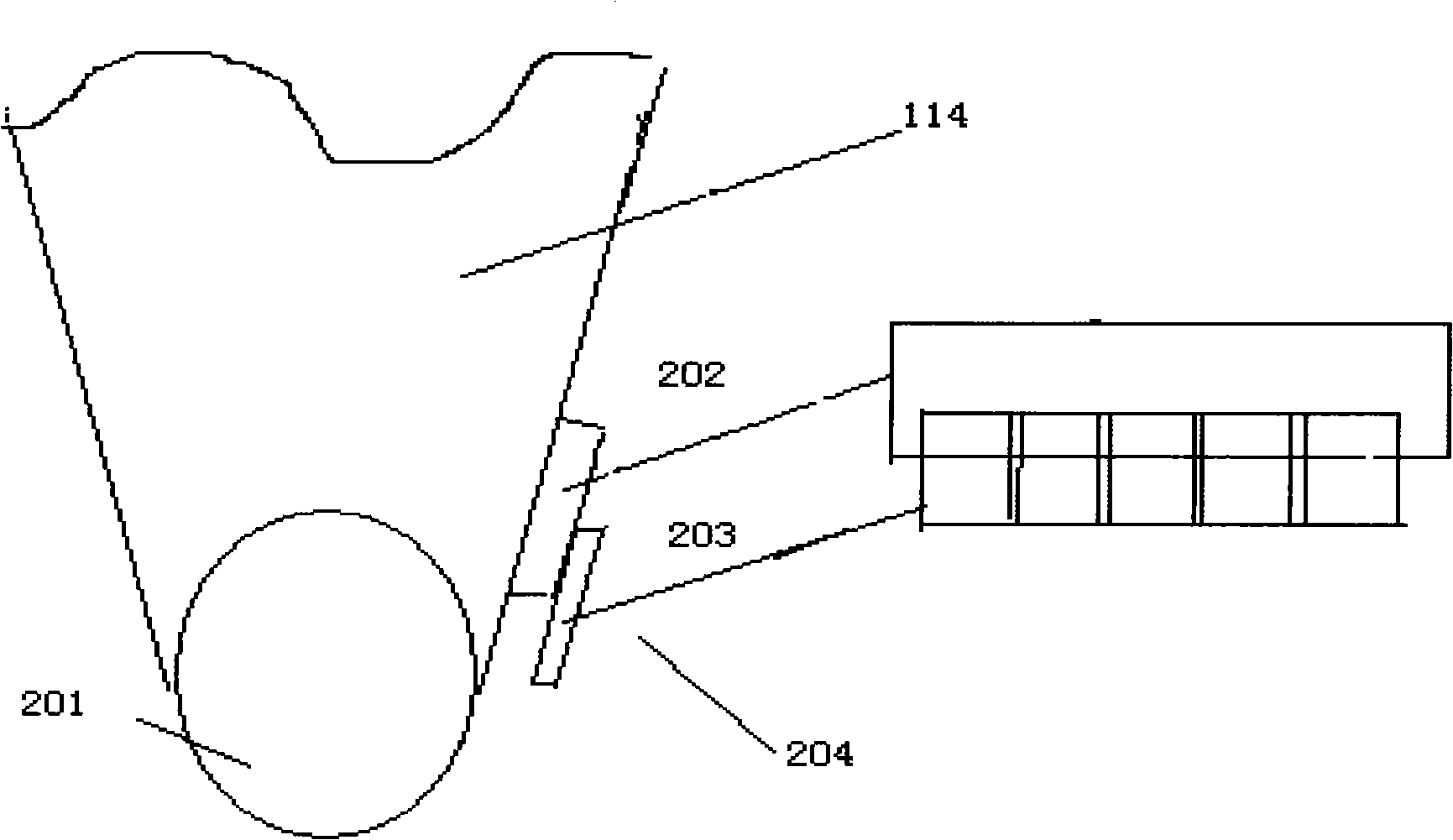
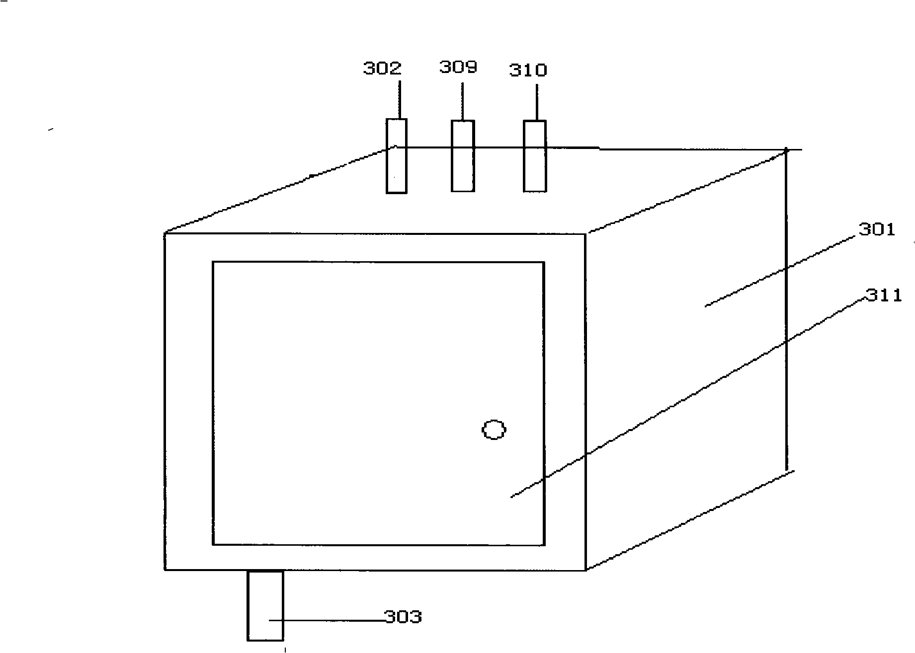
[0027] The invention relates to the positioning detection and control technology of the discharge door of the mixing ore tank in the sintering process. Through the positioning detection of the discharge door of the mixing ore tank, the obtained position information and temperature information of the sinter burn-through point are used to control the mixing ore tank The opening position and degree of the discharge door make the thickness and uniformity of the mixed material arranged on the conveyor belt of the sintering machine reach ideal values, which can well balance the sintering efficiency and quality of the mixed material. In order to solve the problem of harsh on-site environment, the invention seals and integrates the detection element into the dustproof box, and is equipped with air purge and air cooling, which can effectively prevent the influence of on-site dust, high temperature and high humidity on the detection device. In the embodiment of the present invention, the...


PUM


Abstract

The invention provides a controlling device for a mixing ore bin discharging door, which comprises a sealing box (301) and a detecting component group arranged inside the sealing box (301), a gas pipe (302) for conveying gas into the sealing box (301), a pulling rod (303) and a pulling rod window (304) which ensures the pulling rod to extend out of the sealing box (301). One end of the pulling rod (303) is connected with the detecting component group, and the other end thereof extends out of the sealing box (301) through the pulling rod window; by using the controlling device, the corrosion to the detecting component caused by the high temperature, dusty and humid environment in working site can be effectively overcome, the service life can be prolonged and the controlling accuracy can be maintained, and the controlling device is favorable for realizing automatic and accurate controlling of the moving accuracy of the discharging door. The invention also provides a mixing ore bin and a mixing ore bin controlling system.

Description

technical field [0001] The invention relates to a control device and system for a discharge door of a mixing ore tank in a sintering process and a mixing ore tank. Background technique [0002] The sintering process is an important link in the smelting technology, which is used to sinter the powdery mixed raw materials that are not easy to smelt (hereinafter referred to as the mixed material) into sintered ore that is easy to smelt. [0003] figure 1 Schematic diagram of the sintering system. Iron ore powder and auxiliary materials, such as iron ore powder, fuel, flux, ore return, etc., are sent to the mixer 112 through the batching conveyor belt 123 from the batching ore tank 111 and mixed with water. The mixed material mixed with water is sent to the mixed ore tank 114 through the mixed material conveyor belt 113 again. The bottom material of the bottom material ore trough 115 is first laid on the sintering machine conveyor belt 118, the mixed material flowing out from ...

Claims


Application Information

Patent Timeline
IPC IPC(8): C22B1/02F27D3/00B65D88/54G05B19/04G05D3/12
Inventor 田卫红孙英刘勍
Owner ZHONGYE-CHANGTIAN INT ENG CO LTD
Why Eureka
Try Eureka