
Carrier interference noise ratio measurement method and communication apparatus

An interference-to-noise ratio and interference-to-noise technology, applied in the field of communication, can solve the problems of high noise power, low carrier-to-interference noise ratio estimation accuracy, leakage, etc., and achieves the effect of easy processing and improved estimation accuracy

Active Publication Date: 2008-12-31
HUAWEI TECH CO LTD
View PDF0 Cites 13 Cited by
  • Summary
  • Abstract
  • Description
  • Claims
  • Application Information

AI Technical Summary

Problems solved by technology

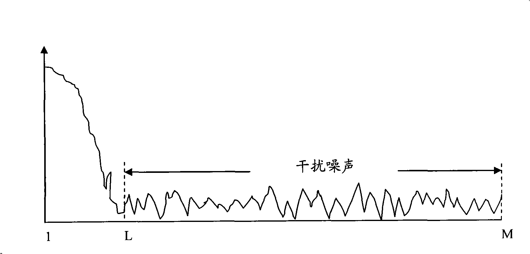
[0014] The contriver finds when researching the present invention, when adopting the above-mentioned scheme, because when obtaining the carrier interference noise power, transforming the signal from the frequency domain to the time domain is equivalent to adding a rectangular window to the frequency spectrum of the signal, thus in the time domain The energy of the channel is not only distributed in the CP (Cyclic Prefix, cyclic prefix) range, but also leaks to the entire range, so that the estimated noise power is too large, especially at a high signal-to-noise ratio. The deviation is large, making carrier interference Estimation of noise ratio is not accurate
At the same time, there is a certain complexity in the implementation

Method used


Image

  • Carrier interference noise ratio measurement method and communication apparatus
  • Carrier interference noise ratio measurement method and communication apparatus
  • Carrier interference noise ratio measurement method and communication apparatus

Examples


Embodiment 1

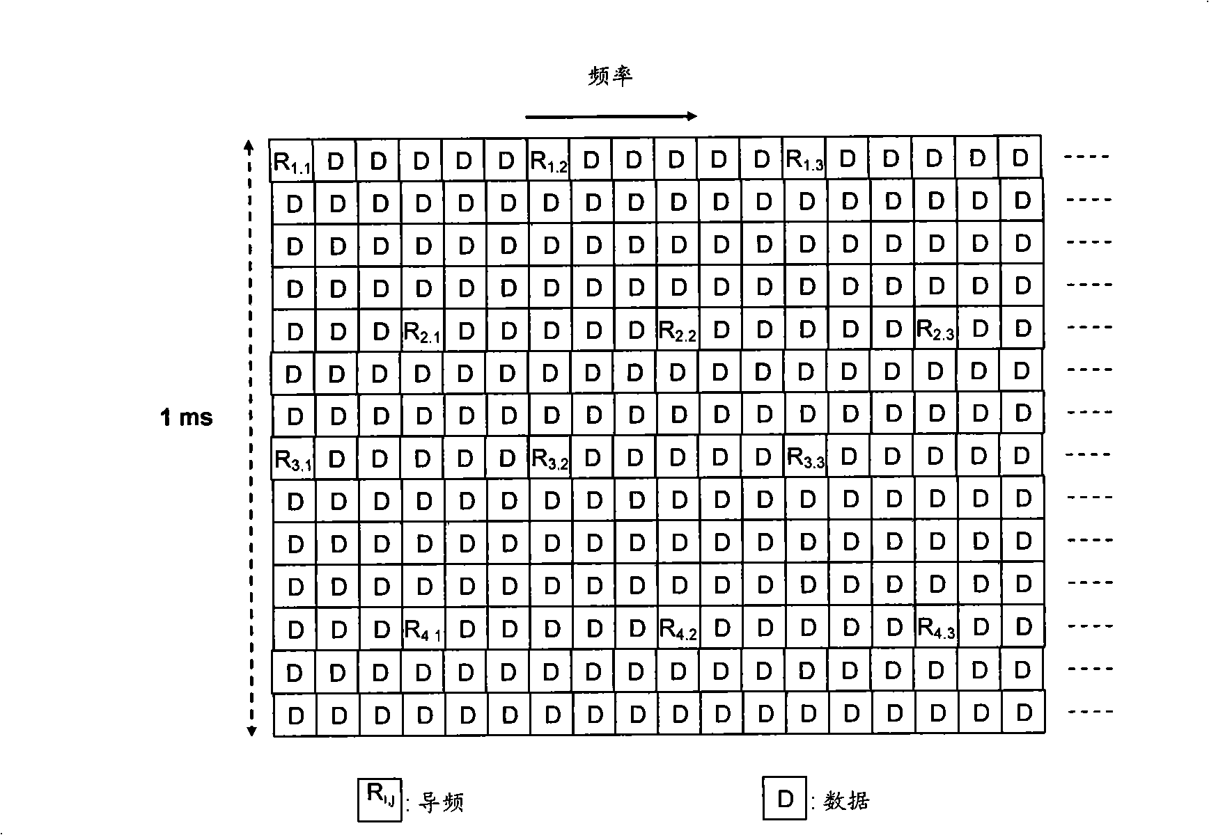
[0046]In the first embodiment, the difference between the estimated channel values ​​of each pair of pilot symbols on the first subcarrier in each pair of subcarriers and the channel value on the second subcarrier of each pair of pilot symbols in the subframe are determined. The difference between the estimated values, and subtract the two differences obtained by each pair of pilot symbols and each pair of subcarriers, and use the result of the subtraction as the interference noise corresponding to each pair of pilot symbols and each pair of subcarriers superposition;

[0047] Obtaining the total interference noise power of the pilot symbols in the subframe according to the superposition of the interference noise;

[0048] The corresponding interference and noise ratio is obtained according to the total interference and noise power and the total power of the pilot symbols in the subframe, and the interference and noise ratio is used as the carrier to interference and noise rat...

Embodiment 2

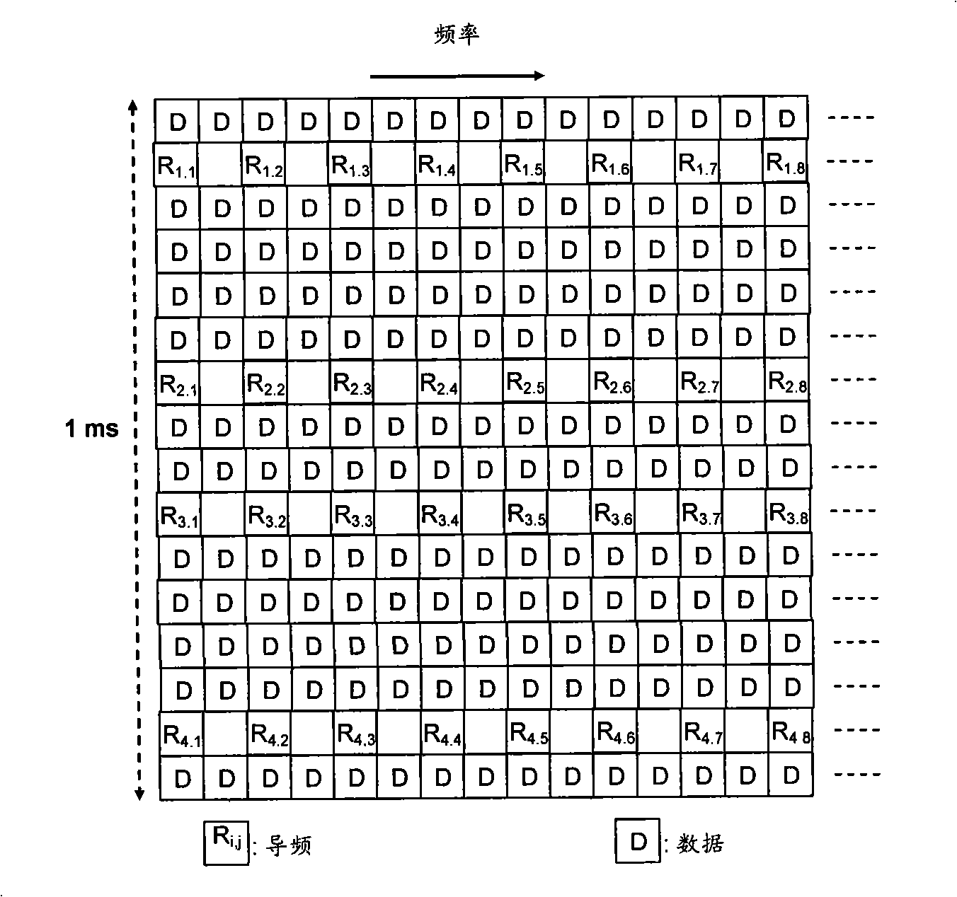
[0090] In the second embodiment, the superposition of the interference noise of each pilot symbol on each subcarrier in the carrier is determined, wherein, the difference between the channel estimation value of a pair of pilot symbols in the two pairs of pilot symbols in the subframe and the channel estimate on the subcarrier value and the difference between another pair of pilot symbols on the subcarrier channel estimate, and the subtraction result is used as the superposition of the interference noise of each pilot symbol on the subcarrier;

[0091] Obtaining the total interference noise power of the pilot symbols in the subframe according to the superposition of the interference noise;

[0092] The corresponding interference and noise ratio is obtained according to the total interference and noise power and the total power of the pilot symbols in the subframe, and the interference and noise ratio is used as the carrier to interference and noise ratio.

[0093] still with ...

Embodiment 3

[0121] The communication device in the third embodiment, such as Figure 9 As shown, it includes a first module 100, a second module 200 and a third module 300, wherein:

[0122] The first module 100 is configured to determine the difference between the channel estimation values ​​of each pair of pilot symbols on the first subcarrier in each pair of subcarriers and the channel estimation value on the second subcarrier of each pair of pilot symbols in the subframe. The difference of the channel estimation value, and subtract the two differences obtained by each pair of pilot symbols and each pair of subcarriers, and use the result of the subtraction as the interference noise corresponding to each pair of pilot symbols and each pair of subcarriers superposition and output;

[0123] The second module 200 is used to obtain and output the total interference noise power of the pilot symbols in the subframe according to the superposition of the received interference noise;

[0124]...


PUM


Abstract

The invention discloses a carrier interference noise ratio measuring method and communication equipment, for advancing estimating accuracy of the carrier interference noise power. In the invention, the difference of a channel estimated value on a first subcarrier and the difference of the channel estimated value on a second subcarrier of each pair of subcarrier are respectively determined in two pairs of pilot frequency signals, and each pair of pilot frequency signal is subtracted from two differences obtained by each pair of subcarriers, wherein the subtracted result is as the overlapping of the interference noises corresponding to each pair of subcarriers. A total interference noise power of the pilot frequency signals is obtained according to the overlapping of the interference noise. Corresponding interference noise ratio is obtained according to the total interference noise power and the total power of the pilot frequency signals in the sub-frame, and the interference noise ratio is as the carrier interference noise ratio. According to the technical project of the invention, estimating accuracy of the carrier interference noise ratio is increased, and process is relatively simpler.

Description

technical field [0001] The invention relates to the communication field, in particular to a method for measuring carrier-to-interference-to-noise ratio and a communication device. Background technique [0002] The 3GPP (3rd Generation Partnership Project, third-generation mobile communication standardization organization) LTE (Long Term Evolution, long-term evolution) project is the largest new technology research and development project launched by 3GPP in recent years. Among them, the uplink multiple access technology adopts SC-FDMA (Single Carrier-Frequency Division Multiplexing Access, single carrier frequency division multiplexing), the downlink adopts OFDMA (Orthogonal Frequency Division Multiplexing Access, orthogonal frequency division multiplexing) multiple access technology. The basic unit of uplink and downlink transmission is a subframe with an interval of 1 millisecond, where the downlink subframe structure is as follows figure 1 As shown, the uplink subframe s...

Claims


Application Information

Patent Timeline
IPC IPC(8): H04Q7/38H04B7/005H04B1/707H04L27/26
Inventor 何龙科
Owner HUAWEI TECH CO LTD
Learn More