Filter bag for vacuum cleaner and production method thereof

A technology for vacuum cleaners and filter bags, which is applied in the field of filter bags, and can solve problems such as cost-intensive, difficult bonding or welding of holding plates, and high cost

Active Publication Date: 2008-12-24
EUROLIFTERS HLDG NV
View PDF2 Cites 10 Cited by
  • Summary
  • Abstract
  • Description
  • Claims
  • Application Information

AI Technical Summary

Problems solved by technology

[0007] However, the aforementioned filter bags have the disadvantage that, with regard to the stability of the base, the high demands in vacuum cleaners and the various shapes of filter bags required do not give satisfactory results every time
Furthermore, the manufacturing method of the filter bag according to DE 103 48 375 A1 is cost-prohibitive and cost-intensive
In addition, the existing seam makes it difficult to glue or weld the retaining plate on the bottom
hard to avoid leaks

Method used


Image

  • Filter bag for vacuum cleaner and production method thereof
  • Filter bag for vacuum cleaner and production method thereof
  • Filter bag for vacuum cleaner and production method thereof

Examples


Embodiment Construction

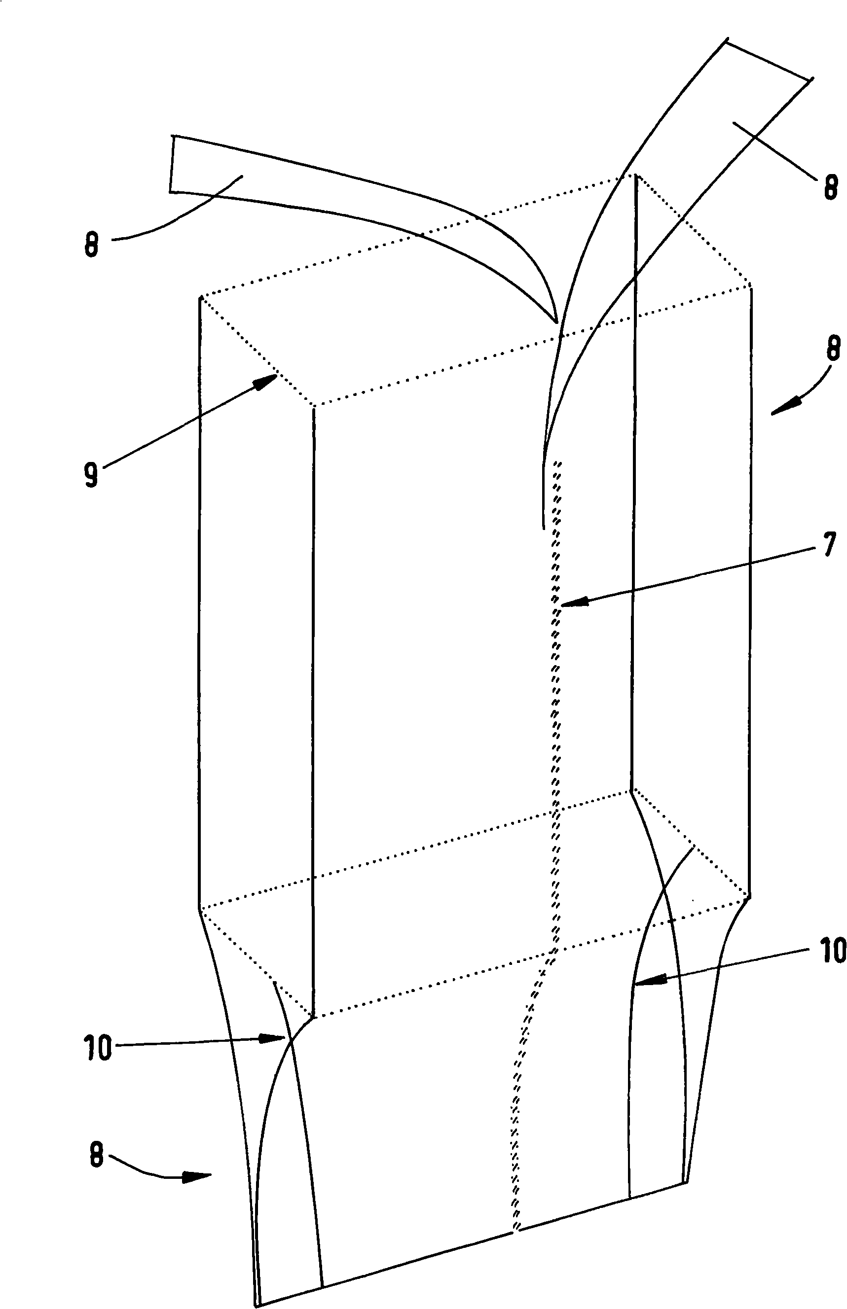
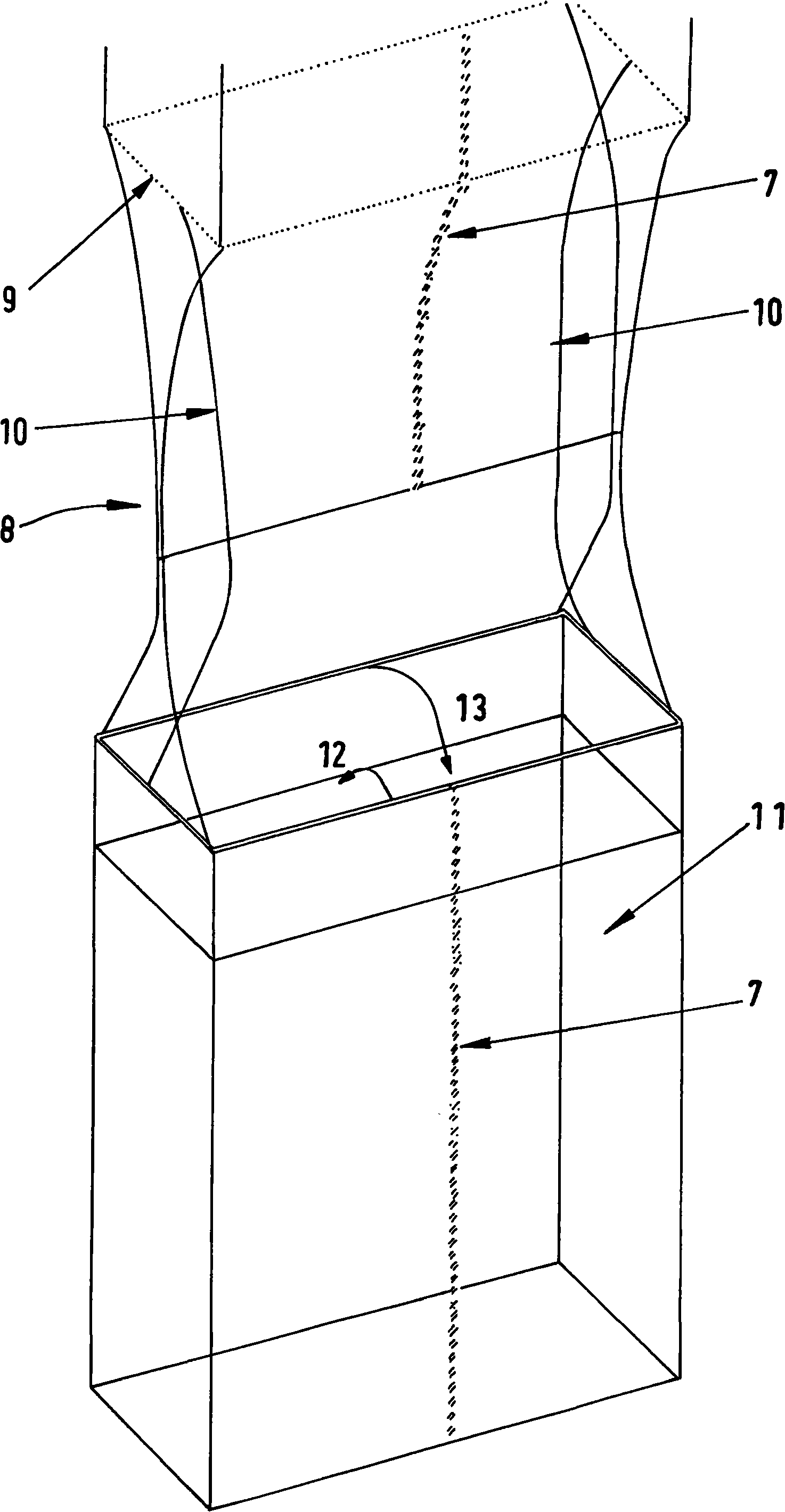
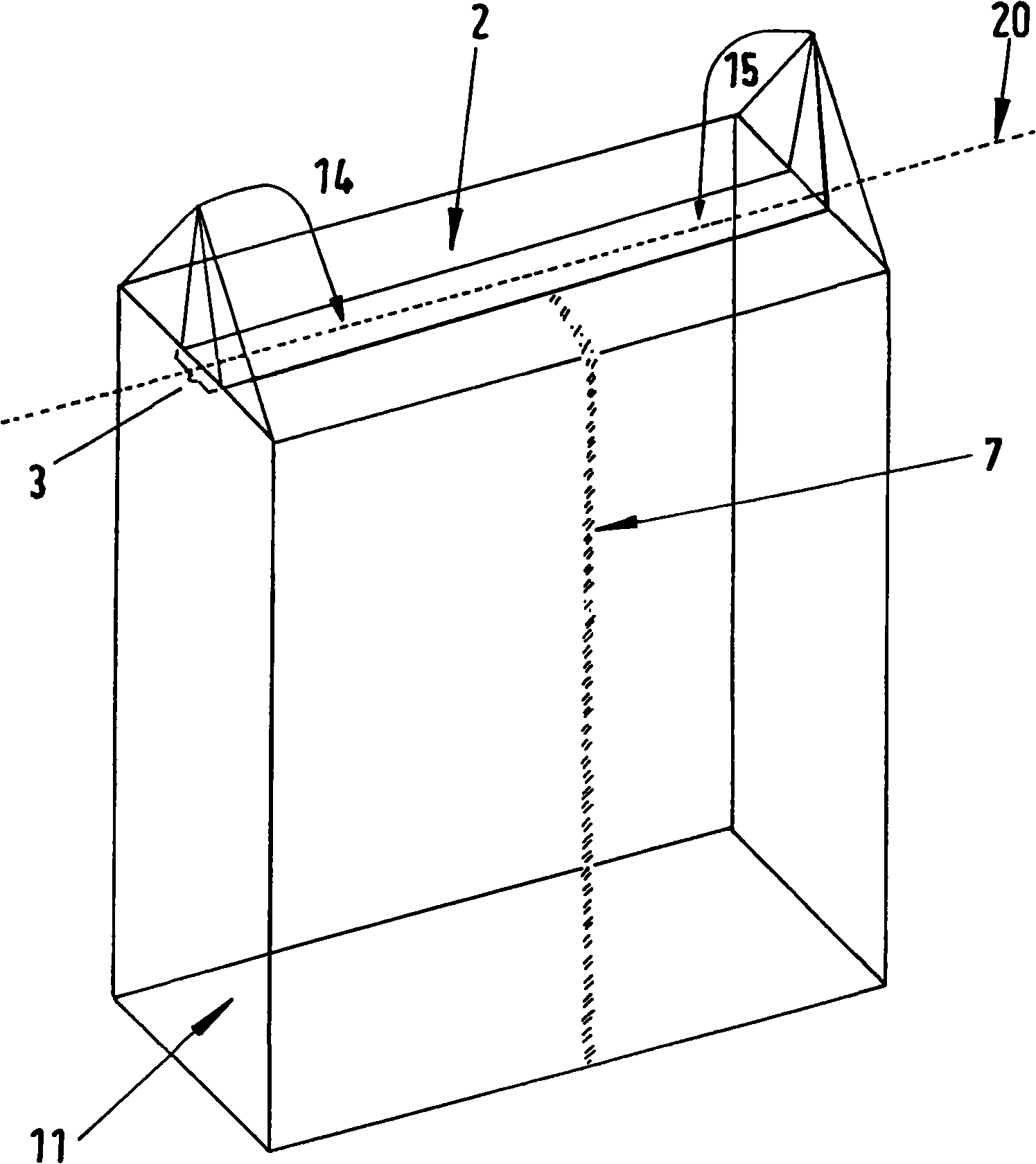
[0032] The sequence of figures 1 to 6 shows the individual steps for producing the filter bag according to the invention according to a first embodiment.

[0033] thus figure 1 A first method step for forming the tube is shown, in which the outer cover 8 is folded over a template 9 defining the shape of the filter bag and the weld seam 7 is then applied in order to form the tube. For example according to figure 1 , the template 9 is formed in the shape of a rectangular box, so that the bottom of the filter bag to be manufactured has a rectangular shape roughly corresponding to the rectangular shape predetermined by the template 9, as shown in the other sequence of figures below. An advantage of the method according to the invention and of the filter bags produced by this method is that, by predetermining the template 9 , filter bags of any shape can be produced with respect to the bottom. for figure 1 The outer covering 8 used in the embodiment shown is a multilayer nonw...


PUM


Abstract

The invention relates to a filter bag for a vacuum cleaner,comprising a tubular bag, which consists of an outer covering that has at least one nonwoven layer, with a first end region (2), which is at least partially sealed and a second sealed end region (5) that lies opposite the first end region. The first end region is folded to form a base. The invention also relates to a method for producing a filter bag of this type.

Description

technical field [0001] The invention relates to a filter bag for a vacuum cleaner comprising a tubular bag consisting of an outer cover having at least one layer of nonwoven material, the tubular bag having an at least partially closed first end region and a A second closed end region opposite the upper region, wherein the first end region is folded to form the bottom. The invention also relates to a method for producing such a filter bag. Background technique [0002] Filter bags for vacuum cleaners are known from the prior art with a tubular bag and a folded bottom except for the closed end region, the so-called block bottom. Typically, such filter bags can also be made from paper stock processed on common tubular bag equipment. In such filter bags, a suitable holding plate with openings through which the air to be cleaned is guided is usually attached to the block-shaped bottom. The task of the block bottom is to stabilize the filter bag and form a three-dimensional ba...

Claims


Application Information

Patent Timeline
Patent Type & Authority Applications(China)
IPC IPC(8): A47L9/14B31B41/00
CPCA47L9/14Y10S55/05Y10S264/48Y10S55/03Y10S55/02Y10T156/1008Y10T156/1007Y10T156/101Y10T156/1011Y10T156/1013B31B2160/00
Inventor 扬·舒尔廷克拉尔夫·绍尔
Owner EUROLIFTERS HLDG NV
Why Eureka
Try Eureka