Under-actuated three-arm non-cooperative target docking capture apparatus
A non-cooperative target and capture device technology, applied in the field of docking capture devices, can solve problems such as extremely high motion control precision, satellite nozzle collision, target satellite flying away, etc., achieve low measurement and motion control precision requirements, and reliable docking High reliability, reliable control effect
- Summary
- Abstract
- Description
- Claims
- Application Information
AI Technical Summary
Problems solved by technology
Method used
Image
Examples
specific Embodiment approach 1
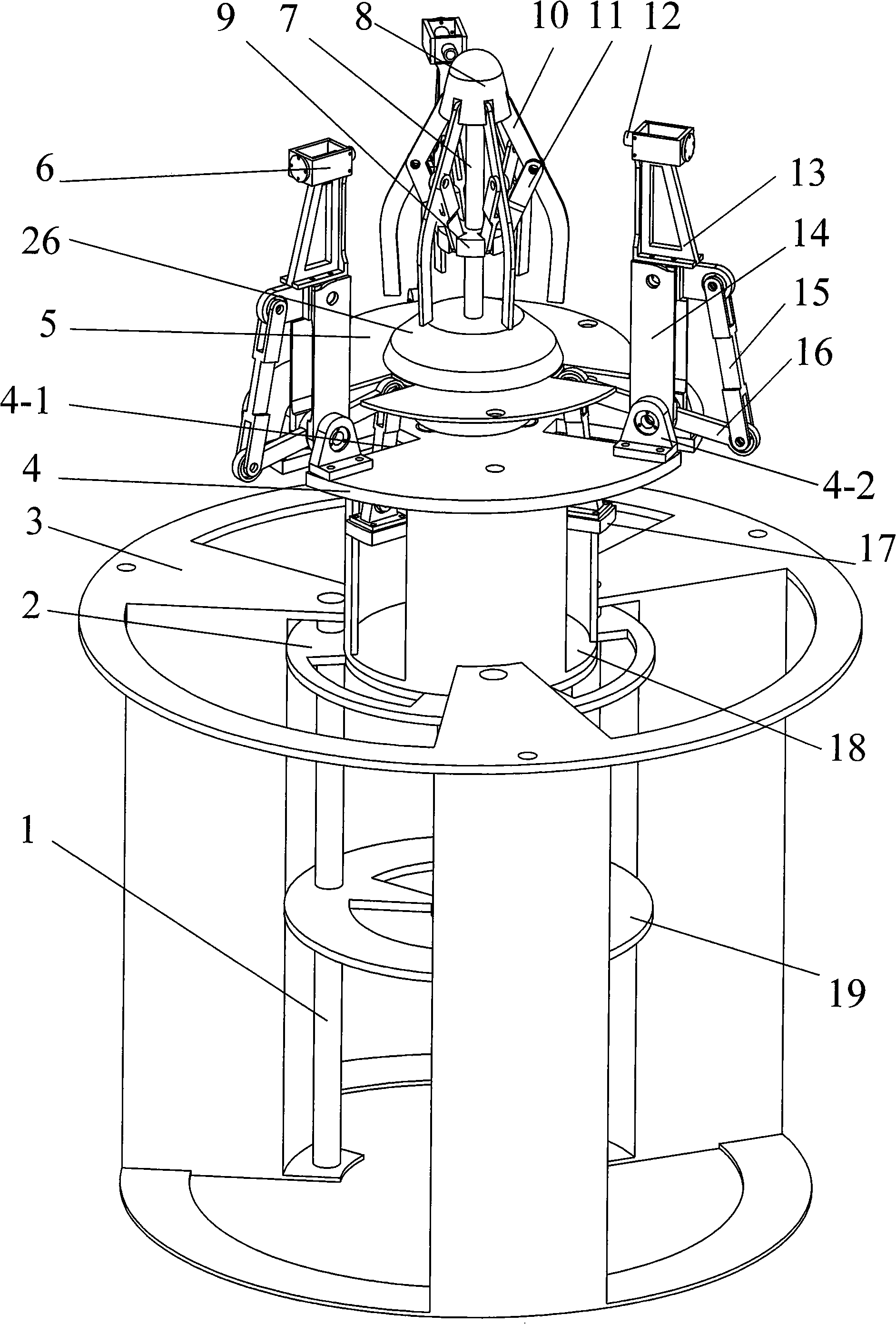
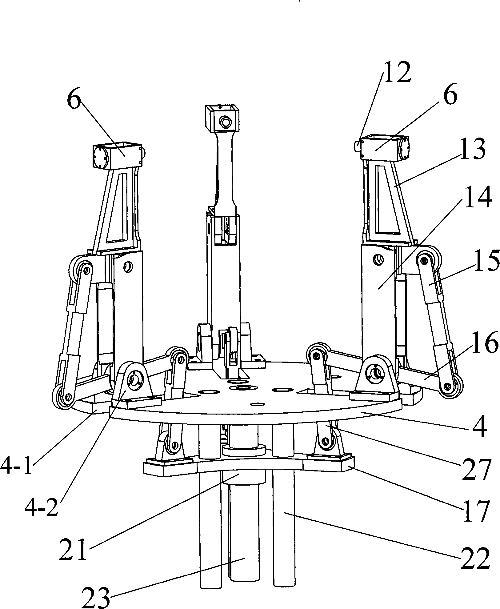
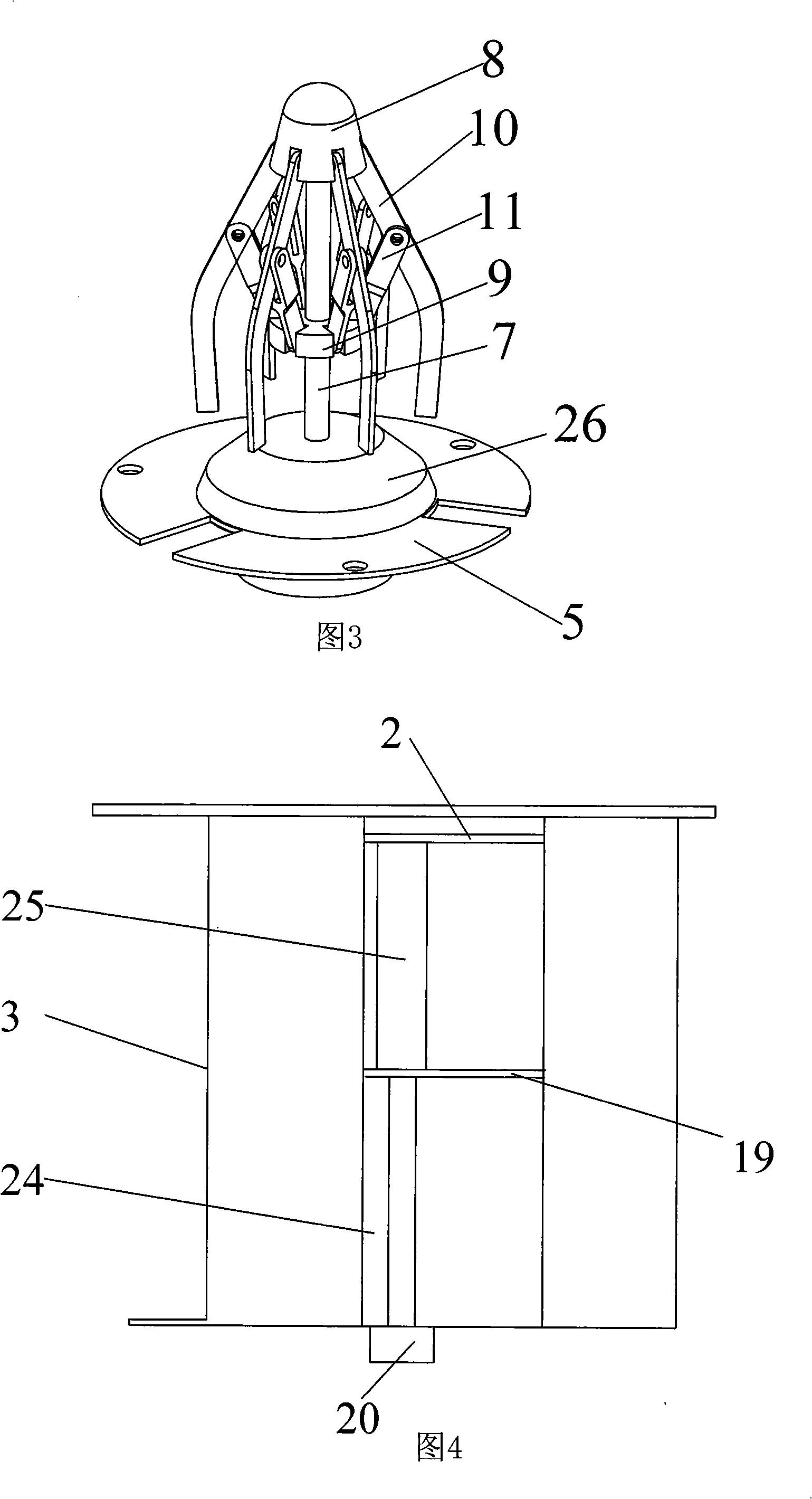
[0009] Specific implementation mode one: as figure 1 As shown in ~3, the underactuated three-arm type non-cooperative target docking capture device described in this embodiment is composed of a lifting mechanism, a front drive capture mechanism and an umbrella buffer mechanism; the front drive capture mechanism includes an underactuated mechanical arm motor 18 , ball screw 23, nut 21, mechanical arm driving plate 17, mechanical arm mounting platform 4, three mechanical arms, and the three mechanical arms are composed of end effector 12, end buffer device 6, upper arm 13, lower arm 14 , the third coupling link 15, the second coupling link 16 and the first coupling link 27; the umbrella buffer mechanism is composed of target docking platform 5, nozzle carrier plate 26, guide column 7, guide slider 9, Three to six buffer connecting rods 11, three to six buffer rods 10 and top cone 8 are formed; the underactuated mechanical arm motor 18 is arranged on the upper end surface of the...
specific Embodiment approach 2
[0012] Specific implementation mode two: as figure 2 As shown, the front drive capture mechanism in this embodiment also includes three manipulator guide posts 22, the upper ends of the three manipulator guide posts 22 pass through the manipulator drive plate 17 and are evenly distributed and fixed on the manipulator installation platform 4 on the lower end face. Three manipulator guide columns 22 are provided, which can play a guiding role, and can further ensure the motion accuracy of the three manipulators. Other components and connections are the same as those in the first embodiment.
specific Embodiment approach 3
[0013] Specific implementation mode three: as figure 1 As shown, the lifting mechanism described in this embodiment is composed of a central bearing cylinder 3, a guide plate 19, three lifting mechanism guide posts 1, a motor 20, a lifting mechanism screw 24, a screw nut 25 and a screw nut plate 2; The three lifting mechanism guide columns 1 respectively pass through the guide plate 19 located in the center bearing cylinder 3 and are evenly distributed in the center bearing cylinder 3, and the two ends of the three lifting mechanism guide columns 1 are respectively fixed on the two ends of the center bearing cylinder 3. On the inner wall of the end, the lifting mechanism screw rod 24 is located in the center bearing cylinder 3 and passes through the middle part of the guide plate 19. The lower end of the lifting mechanism screw rod 24 is connected with the output shaft of the motor 20, and the screw nut 25 is sleeved on the lifting mechanism screw rod 24. Above, the screw nut...
PUM
 Abstract
Description
Claims
Application Information
 - R&D Engineer
- R&D Manager
- IP Professional
- Industry Leading Data Capabilities
- Powerful AI technology
- Patent DNA Extraction
Browse by: Latest US Patents, China's latest patents, Technical Efficacy Thesaurus, Application Domain, Technology Topic, Popular Technical Reports.
© 2024 PatSnap. All rights reserved.Legal|Privacy policy|Modern Slavery Act Transparency Statement|Sitemap|About US| Contact US: help@patsnap.com


