
Clockwork spring braking energy recovery device

A spring and axle technology, applied to vehicle components, transportation and packaging, brake components, etc., can solve the problems of impracticality, heavy energy recovery device, high cost, etc., and achieve compact and convenient structure, high energy recovery efficiency and simple structure Effect

Inactive Publication Date: 2008-12-24
KUNMING UNIV OF SCI & TECH
View PDF0 Cites 9 Cited by
  • Summary
  • Abstract
  • Description
  • Claims
  • Application Information

AI Technical Summary

Problems solved by technology

These two types have energy loss in the process of energy conversion, and the structure is more complicated and the cost is higher
The best energy recovery method is mechanical energy storage, but it is unrealistic to use it on current fuel-powered vehicles, because the structure of mechanical energy storage is huge and the energy recovery device is too heavy

Method used


Image

  • Clockwork spring braking energy recovery device
  • Clockwork spring braking energy recovery device
  • Clockwork spring braking energy recovery device

Examples


Embodiment Construction

[0011] The present invention will be further described below in conjunction with drawings and embodiments.

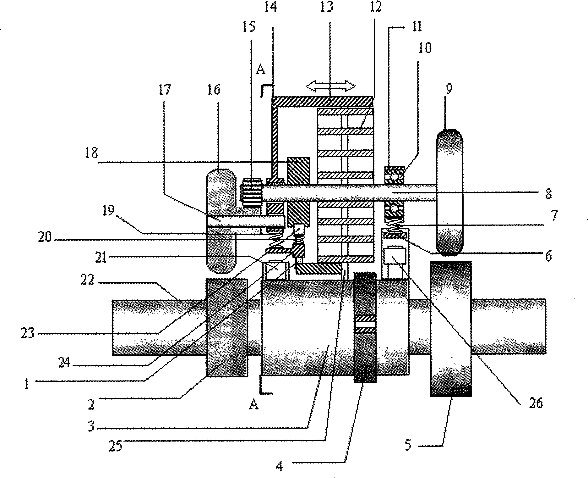
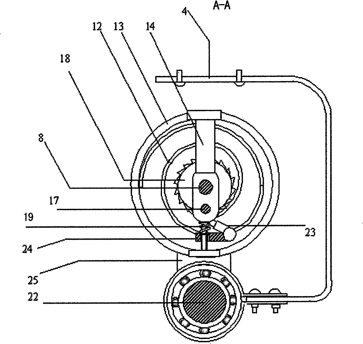
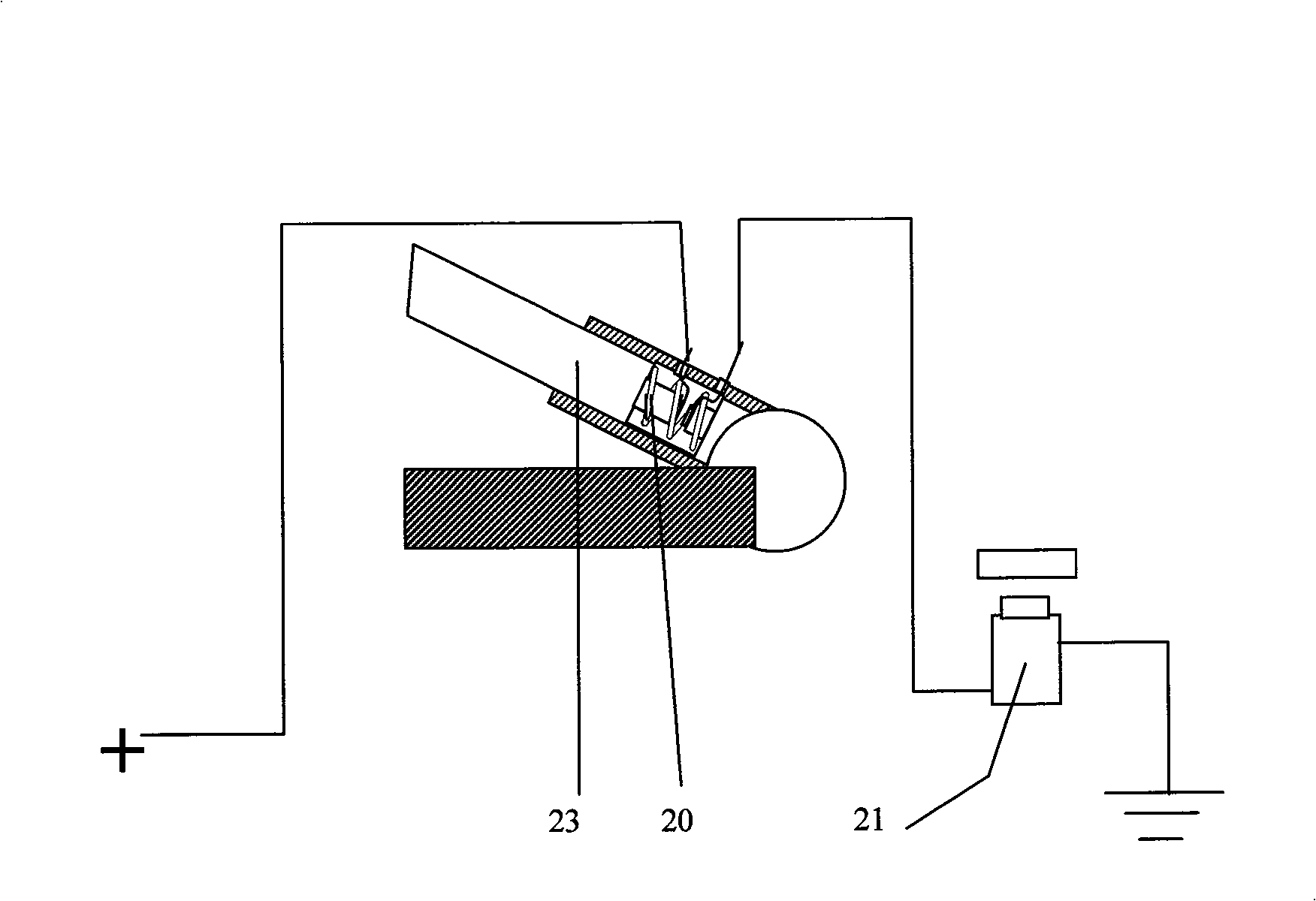
[0012] see Figure 1~3 , the clockwork brake energy recovery device is mounted on the axle 22 by the outer shaft sleeve 3 of the spring brake brake energy recovery device, and the spring brake energy recovery device fixing frame 4 is fixedly connected with the bottom plate of the car to prevent the spring brake from returning to the vehicle. The device can rotate as a whole. The outer end of clockwork spring 12 is welded together with spring housing 13; the inner end is welded together with spring shaft 8, so that a spring energy storage device can be formed. The lower end of the spring casing 13 is welded with the swing shrapnel 25, and the swing shrapnel 25 is welded together with the outer shaft casing 3 of the spring brake energy recovery device, so that the spring casing 13 and the spring brake energy recovery device outer shaft sleeve 3 are welded together. Betw...


PUM


Abstract

The present invention relates to a spring energy-collecting device which can be used for storing, releasing and using the energy of vehicle brake, and belongs to the technological field of carrying tools. In the technical proposal, a vehicle shaft is dynamically provided with a fitting external shaft lining pipe, and is fixedly provided with a torque input rubber wheel and a torque output rubber wheel; the external shaft lining pipe is connected with the spring shell through a swinging shrapnel; the spring shaft is respectively provided with an upper spring rubber wheel which exactly faces the torque output rubber wheel, an output gear which is connected with a spring output rubber wheel in the way of transmission, a one-way ratchet; the spring output rubber wheel exactly faces the torque input rubber wheel; the external shaft lining pipe is provided with an electromagnet, which is arranged close to the torque output rubber wheel and provided with an open-close contact arranged in the position of the brake; an electromagnet is arranged close to the torque input rubber wheel and provided with open-close contact arranged in the position of the accelerator. The spring energy-collecting device has the advantages of simple structure, small loss of energy and light weight, and is suitable for light electric vehicles.

Description

technical field [0001] The invention relates to an energy recovery device for storing and releasing the energy of vehicle braking, in particular to a spring brake energy recovery device, which belongs to the technical field of vehicles. Background technique [0002] At present, there are two main types of braking energy recovery methods: one is to drive a generator to generate electricity from the braking energy and store the electric energy; the other is to convert the braking energy into compressed air energy for storage. These two types have energy loss in the process of energy conversion, and the structure is more complicated and the cost is higher. The best energy recovery method is mechanical energy storage, but it is unrealistic to use it on current fuel vehicles, because the structure of mechanical energy storage is huge and the energy recovery device is too heavy. Therefore, for light-duty electric vehicles, it is necessary to find an energy recovery device with hi...

Claims


Application Information

Patent Timeline
IPC IPC(8): B60T1/10
Inventor 陈蜀乔代丽梅
Owner KUNMING UNIV OF SCI & TECH
Learn More