


Quick Research
Generate reliable direction feasibility study reports for your R&D in just a few steps.

Technical Q&A
Discover and master advanced knowledge NOW. Basics, ideas, possibilities, all at once.

Find Solutions
As an expert in R&D theories, this can generate solutions to your technical problems instantly.

Evaluate Feasibility
Analyze your overall solution with one click, know your potential R&D risks in advance.

Monitor Landscape
Get weekly tech updates, stay abreast of the latest tech innovations and key insights.
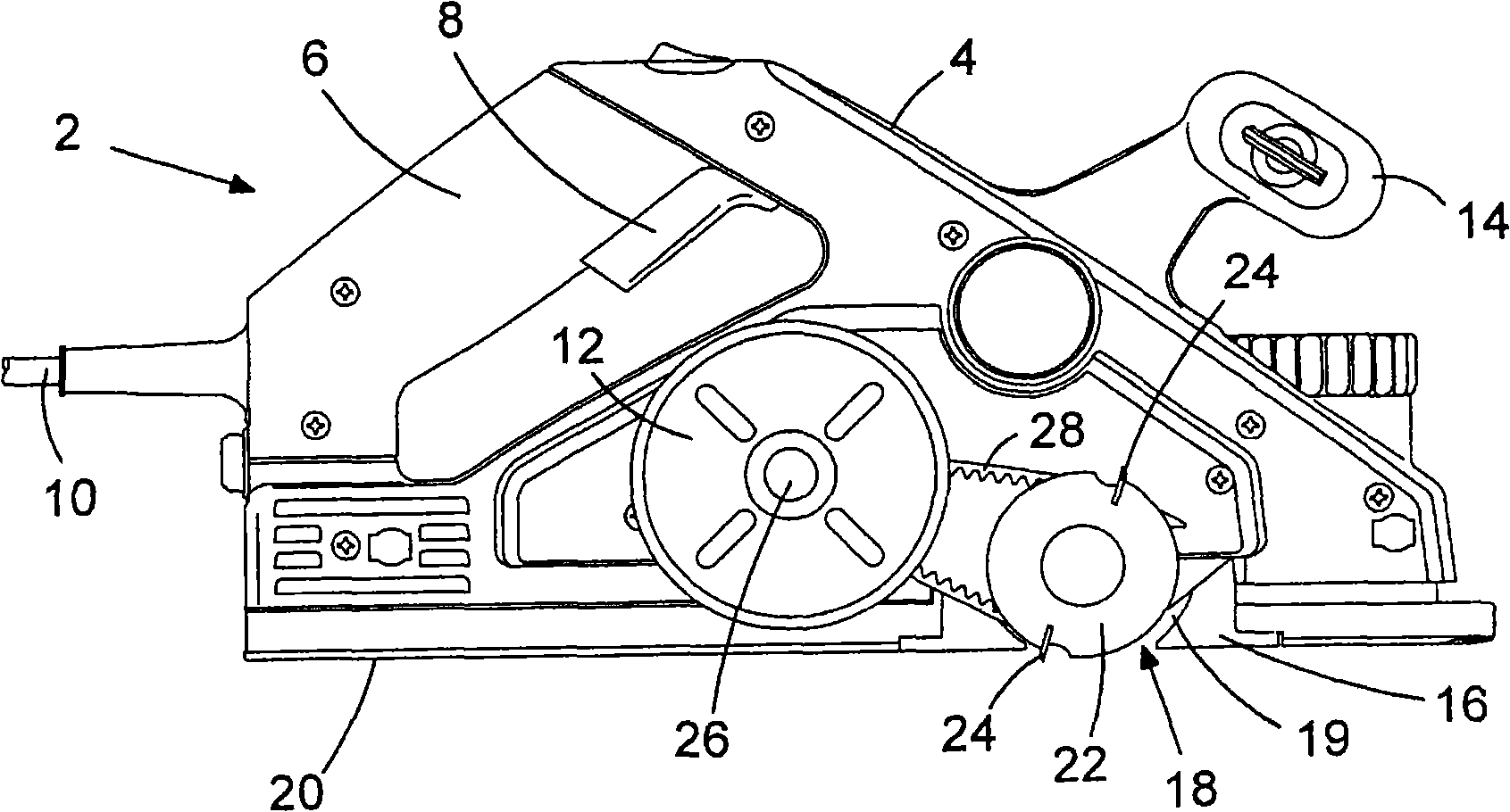
Power planer
A planer and motor technology, which is applied to manual planers, synchronizing machine parts, and processing machines for manufacturing flat surfaces, etc., can solve the problems of insufficient space in the shell 4, hindering the effective use of the planer, and the large size of the planer, etc. Achieve the effect of compact structure, easy arrangement and large motor torque
- Summary
- Abstract
- Description
- Claims
- Application Information
AI Technical Summary
Problems solved by technology
Method used
Image

Examples
Embodiment Construction
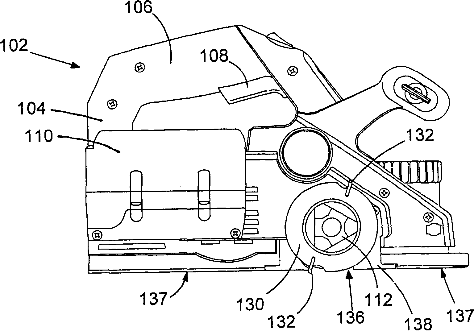
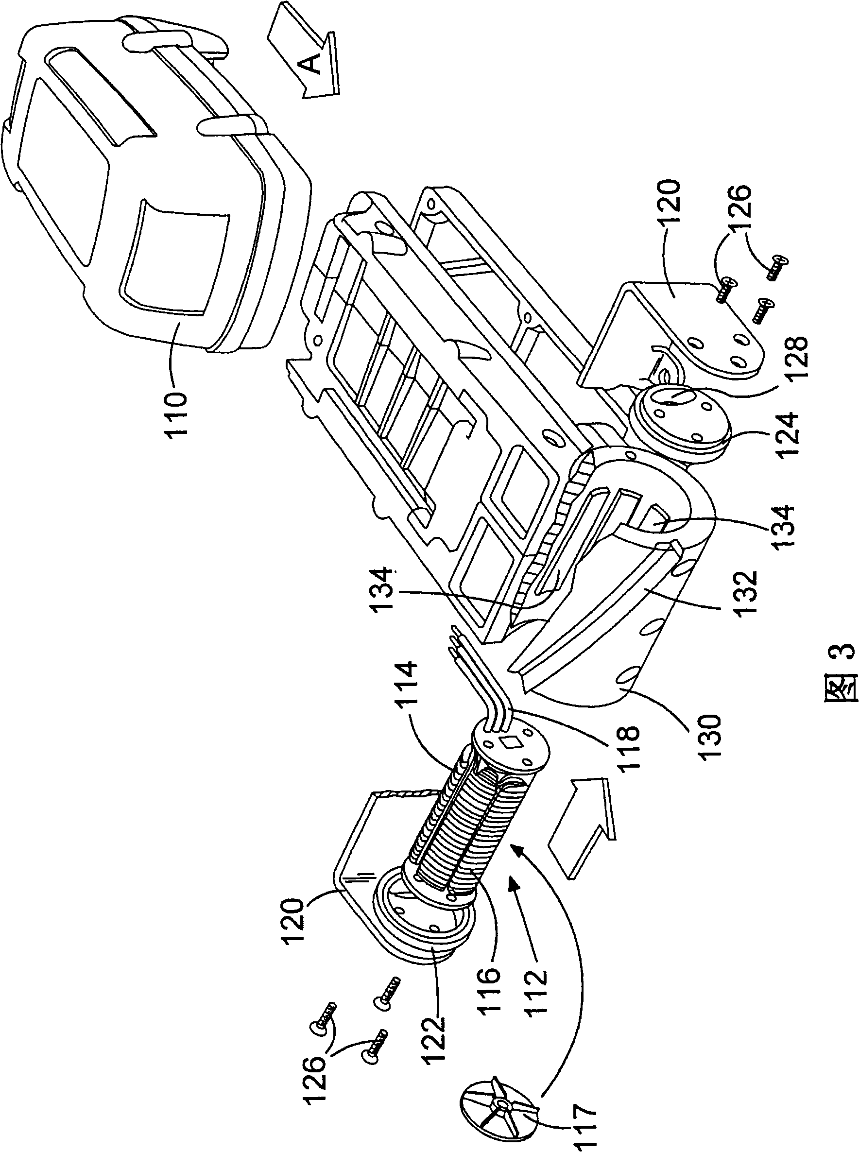
[0052] exist figure 2A battery powered hand planer 102 embodying the present invention is shown in FIG. 3 . The planer 102 has a housing 104 defining a rear handle 106 with a trigger switch 108 for supplying power from a rechargeable battery 110 to an electric motor 112 and including a workpiece engaging surface 137 that is in use when the planer is in use. Lean against the workpiece while in the middle.
[0053] As shown in more detail in FIG. 3 , the motor 112 is a brushless motor having a central stator 114 carrying a field winding 116 connected to the battery 110 via a power module (not shown) that controls the timing of energization of the field winding 116 . The wire 118 is energized. Stator 114 is secured to bracket 120 on housing 104 by end caps 122 , 124 and screws 126 such that stator 114 is non-rotatably mounted relative to housing 104 . One 124 of the end caps has an elongated hole 128 for allowing connection of wires 118 to the power module.
[0054] The elec...
PUM
 Abstract
Description
Claims
Application Information
 - R&D Engineer
- R&D Manager
- IP Professional
- Industry Leading Data Capabilities
- Powerful AI technology
- Patent DNA Extraction
Browse by: Latest US Patents, China's latest patents, Technical Efficacy Thesaurus, Application Domain, Technology Topic, Popular Technical Reports.
© 2024 PatSnap. All rights reserved.Legal|Privacy policy|Modern Slavery Act Transparency Statement|Sitemap|About US| Contact US: help@patsnap.com