Resonance drive modular control method with dynamic power supply

A control method and technology for driving modules, which are applied to electrical components, high-efficiency power electronic conversion, and output power conversion devices, etc., can solve the problem of high saturation on-resistance Rds of switching tubes, increased inductance cores, and increased conduction losses. And other issues

Inactive Publication Date: 2011-11-16
深圳市美吉星集成科技有限公司
View PDF0 Cites 1 Cited by
  • Summary
  • Abstract
  • Description
  • Claims
  • Application Information

AI Technical Summary

Problems solved by technology

How to reduce the driving power consumption ΔPg? Selecting a power electronic switching tube with a small Ci may lead to a higher saturated on-resistance Rds(ON) of the switching tube and increase the conduction loss; reducing the frequency may lead to an increase in the inductance core; the most effective and active method should pay attention to Reduce the driving voltage Ugs

Method used


Image

  • Resonance drive modular control method with dynamic power supply
  • Resonance drive modular control method with dynamic power supply
  • Resonance drive modular control method with dynamic power supply

Examples


Embodiment Construction

[0015] The technical solution of the present invention will be described in further detail below in conjunction with the accompanying drawings.

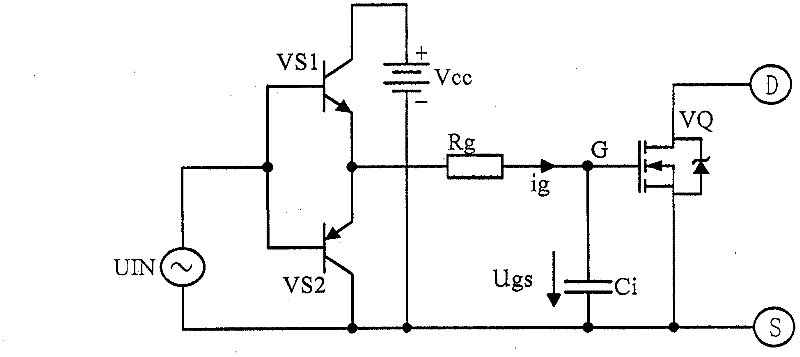
[0016] from image 3 It can be seen that when the input is high, V s1 (NPN transistor) from the floating supply V on Obtain the collector current Ic, output Ie from the emitter, and supply power to the capacitive load Ci through the current limiting resistor Rg, which is to drive the power electronic switch V Q The driving voltage Ugs. And when the input is low, V s2 (PNP transistor) is turned on, and the charge stored in the capacitive load Ci is limited by the resistor Rg, and then by V s2 (PNP transistor) The tube is turned on and discharged. Thus, the power supply V on The drive power consumption is all consumed in the heat generation of the resistor Rg. In addition, both NPN transistors and PNP transistors are hard switches, and there is a risk of shoot-through, which may cause the power supply V on short circuit hazard....


PUM


Abstract

The present invention provides a resonance drive module control method with a dynamic power, adopting the technical scheme: the traditional hard switch drive is improved to the resonance soft switch drive, the dynamic power +Von capacitance pump lower than Ugs is used to supply power to drive the voltage Ugs, in the non-driving period, the grid voltage Ugs is -Voff negative bias, which effectively overcomes Ci 'the Miller effect', reduces the feedthrough harm of the half bridge or the full bridge; the capacitance pump of the power Von in the driving period and the capacitance pump of the -Voff in the non-driving period are all supplied with power by a secondary winding of an isolating transformer, namely the transformer transmits the driving frequency f, also transmits the two dynamic capacitance pump power +Von and -Voff. The invention has the advantages of strong interference killing feature, higher reliability of the negative bias drive of the combination module, little loss, high efficiency and excellent performance price ratio.

Description

technical field [0001] The invention relates to a control method of a switching power supply, in particular to a control method of a low-loss resonant drive module specially used for non-common-ground power electronic switch drive. Background technique [0002] The most important part of the switching power supply is the power electronic switch, which is the key part of the weak current control of the strong current. It can be expressed by the D pole and the S pole representing the strong current switch and the G pole representing the weak current drive. See figure 1 shown. When the gate is applied with a high-level drive voltage Ugs (generally not exceeding 20 volts), see figure 1 t in (C) 1 to t 2 , T 3 to t 4 , t 5 to t 6 Period, so that the power electronic switch is controlled by strong current, so ids indicates that the power electronic switch is turned on (ON), and in the period when there is no driving voltage Ugs (no control signal), see figure 1 Period t in...

Claims


Application Information

Patent Timeline
Patent Type & Authority Patents(China)
IPC IPC(8): H02M1/08
CPCY02B70/1491Y02B70/10
Inventor 申莉萌王希天
Owner 深圳市美吉星集成科技有限公司
Why Eureka
Try Eureka