
Diffuse multilayer optical assembly

A technology of optical components and light diffusion layers, applied in the fields of optical films and optical displays, can solve the problems of reduced revenue, reduced total output, and increased system cost

Inactive Publication Date: 2008-12-10
3M INNOVATIVE PROPERTIES CO
View PDF18 Cites 19 Cited by
  • Summary
  • Abstract
  • Description
  • Claims
  • Application Information

AI Technical Summary

Problems solved by technology

However, from a manufacturing standpoint, handling and assembling several separate membrane sheets presents various problems
These issues include the extra time required to remove the protective liner from each optical film and increased chances of damaging the film when removing the liner
In addition, inserting multiple individual sheets into the display frame is time consuming, and stacking individual films further provides the opportunity to damage the film
All of these issues can result in lower overall yields or lower yields, resulting in higher system costs

Method used


Image

  • Diffuse multilayer optical assembly
  • Diffuse multilayer optical assembly
  • Diffuse multilayer optical assembly

Examples


example 1

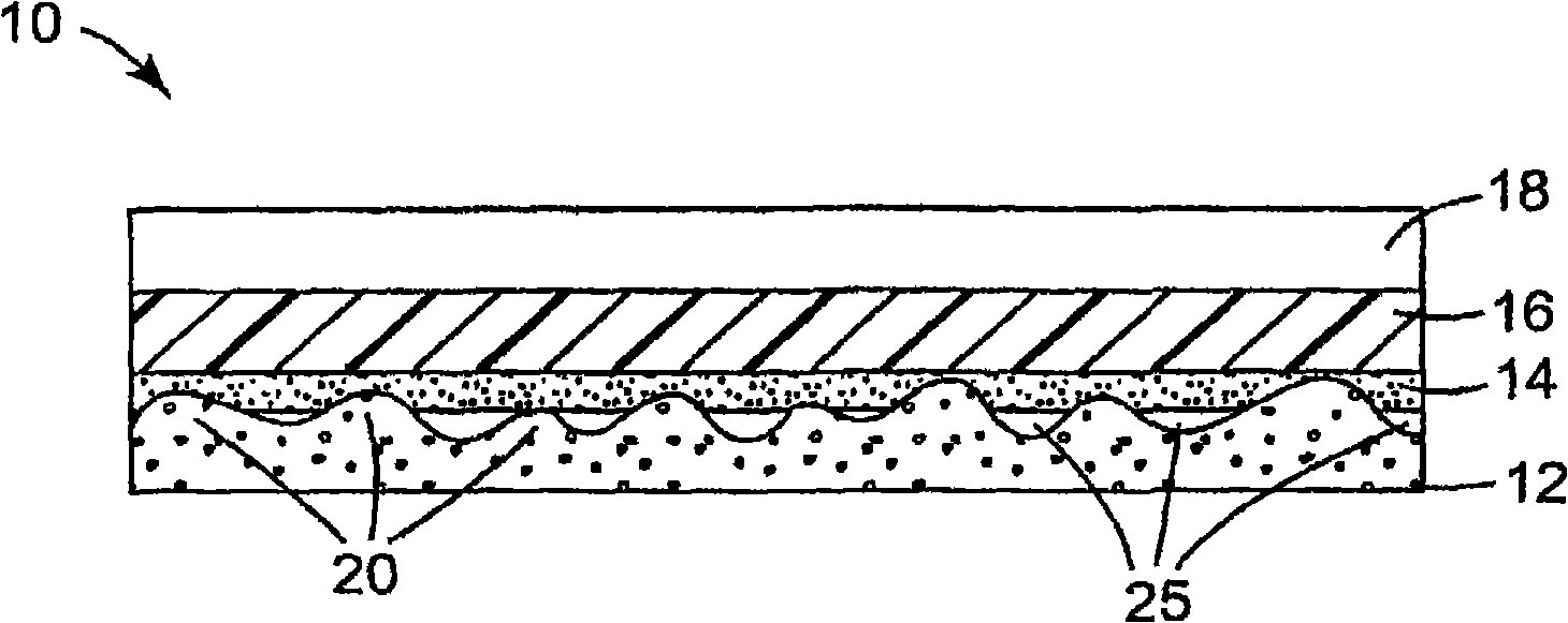
[0077] The reflective polarizer used is 1 / 2 - D400, the reflective polarizing layer is 3M laminated to a sheet of approximately 130 μm thick polycarbonate (60% haze) using a radiation-curable adhesive TM Vikuiti TM Reflective Polarized Brightness Enhancement Film (DBEF-Q). Polycarbonate has a matte surface. The light-diffusing layer was a 2.0 mm light-diffusing plate with a non-uniform surface, model RM802, available from Sumitomo Chemical Company, Tokyo, Japan. The light diffusion layer includes a copolymer of methyl methacrylate and styrene (hereinafter referred to as MS). The surface properties of Surface 1 and Surface 2 of the RM802 light-diffusing layer measured using a stylus profiler are shown in Table 1 below. The reflective polarizing layer was attached to Surface 1 of the light diffusing layer using an approximately 15 μm thick layer of pressure sensitive adhesive (Adhesive A) manufactured by 3M Corporation, Saint Paul, Minnesota. Adhesive A is composed of 9...

example 2

[0081] Example 2 was prepared as described in Example 1, except that the reflective polarizing layer included approximately 250 μm thick polycarbonate layers laminated to both sides of the DBEF-Q film, and BEFIII 90 / 50 overlying one polycarbonate layer , 7R (that is, the radius of curvature is 7 μm) prism (the reflective polarizing layer is DBEF-DTV).

example 3

[0083] Example 3 was prepared as described in Example 1 except that the reflective polarizing layer used was a DBEF-Q film without the approximately 130 μm thick polycarbonate sheet laminated thereon.


PUM


Abstract

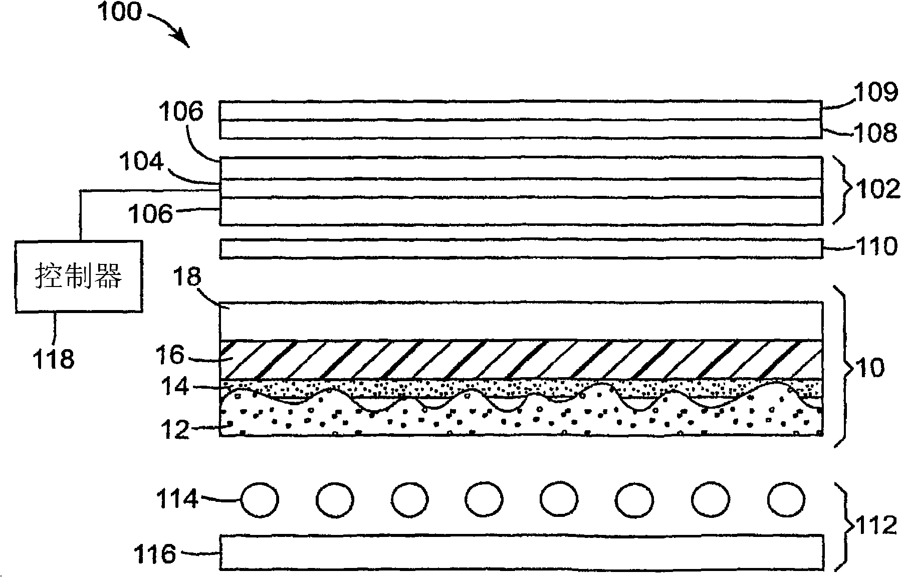
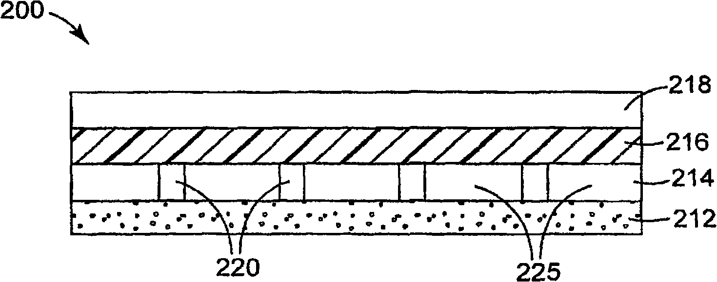
An optical assembly includes a light diffusing layer attached to a reflective polarizing layer. An intermediate region between the light diffusing layer and the reflective polarizing layer includes an intermediate structure that defines voids between the light diffusing layer and the reflective polarizing layer.

Description

Background technique [0001] The present invention relates to optical films and optical displays incorporating the optical films. In particular, the present invention relates to a multilayer optical assembly comprising a reflective polarizing layer attached to a light diffusing layer and defining a void in an intermediate region between the diffusing layer and the reflective polarizing layer. [0002] Optical displays such as liquid crystal displays (LCDs) are becoming increasingly common and are used in, for example, mobile phones, handheld computing devices such as personal digital assistants (PDAs) and video game consoles, and large devices such as laptop computers , LCD monitor and LCD TV screen). Incorporation of light management films into optical display devices results in improved display performance. Different types of films, including prismatic structured films, reflective polarizers, and diffusers, can be used to improve display parameters such as output brightness...

Claims


Application Information

Patent Timeline
IPC IPC(8): G02B5/30G02B5/02B32B27/00B32B7/023
CPCB32B27/08G02B5/0231G02B5/0242G02B5/0247G02B5/0278G02B5/305C09K2323/00B32B7/023G02B5/02G02B5/30B32B7/12B32B3/26B32B2457/202B32B2307/416B32B2307/414B32B2307/42B32B2551/00
Inventor 瑞安·T·法比克斯蒂芬·J·埃茨科恩马克·D·格尔森
Owner 3M INNOVATIVE PROPERTIES CO
Learn More