Cutting rod, cutting bit and cutting tool

A technology of drill pipes and drill bits, which is applied in the field of drill bits, drilling tools and drill pipes. It can solve the problems of increased load on drilling tools, thinning of drill bit wall thickness, and drill bit residue, etc., to suppress breakage, ensure wall thickness, and process easy effect

Inactive Publication Date: 2012-07-18
MITSUBISHI MATERIALS CORP +1
View PDF3 Cites 0 Cited by
  • Summary
  • Abstract
  • Description
  • Claims
  • Application Information

AI Technical Summary

Problems solved by technology

However, in conventional drilling tools, the diameter of the attachment part of the drill rod is set small in order to ensure the wall thickness of the drill bit. , in the case of increasing the drilling speed, the load acting on the drilling tool increases, and there is a risk of damage to the drill pipe due to this load
On the other hand, in the case of increasing the diameter of the drill rod, the wall thickness of the drill bit becomes thinner, so there is a problem of bit breakage
In particular, when the drill rod is broken, the drill bits and the like remain at the bottom of the drilled hole, and it takes a lot of time and labor to repair the accident, so it is not economical.

Method used


Image

  • Cutting rod, cutting bit and cutting tool
  • Cutting rod, cutting bit and cutting tool
  • Cutting rod, cutting bit and cutting tool

Examples


Embodiment

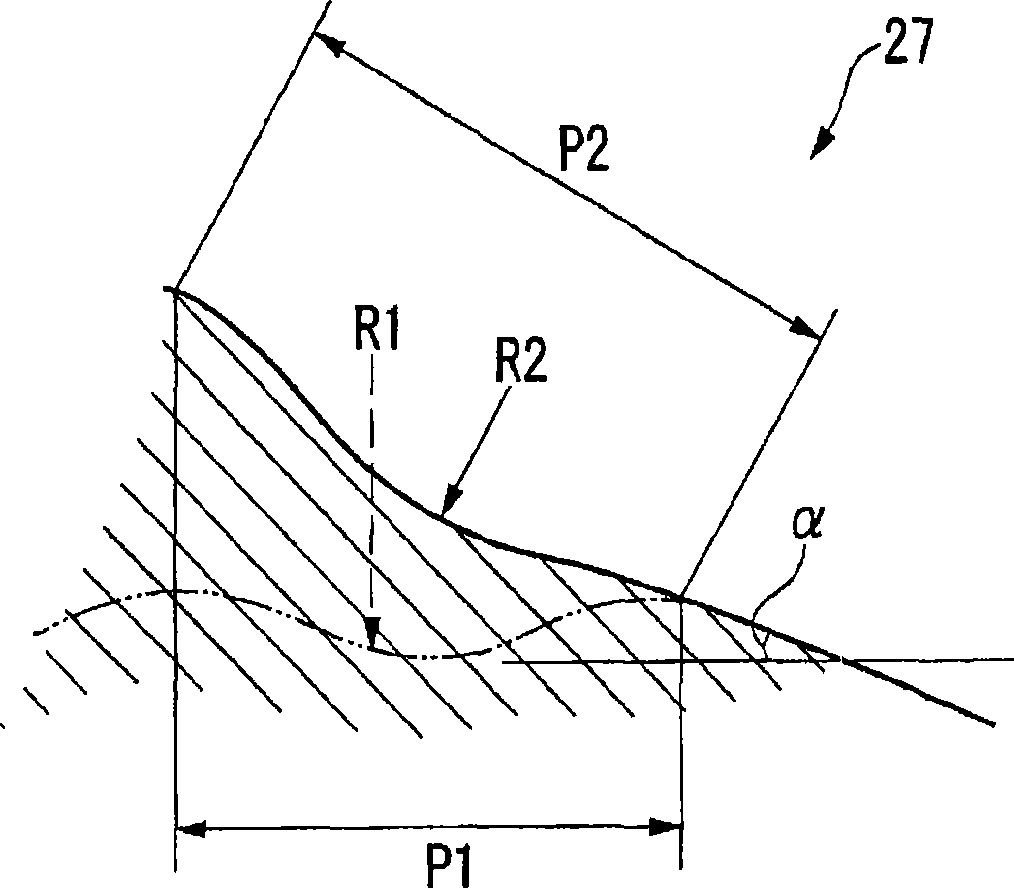
[0108] The result of studying the length l1 of the parallel male thread portion in the present invention will be described below.

[0109] In consideration of the rigidity of the drill rod, the length L1 of the parallel male thread portion obtained by cutting off the outer peripheral surface of the drill rod is preferably short. In particular, the portion that is subjected to a bending load during drilling and is long in length from the tip and small in outer diameter has the greatest stress and is likely to cause breakage, so the length of the parallel male thread portion forming the thread groove is preferably short.

[0110]On the other hand, axial loads applied by rotational force and thrust act on the thread portion. Therefore, in consideration of the load applied to each thread, it is preferable that the number of threads is large and the length L1 of the parallel male thread portion be long.

[0111] Therefore, FEM analysis was performed on the length of the parallel m...


PUM


Abstract

The present invention provides a drilling rod, a drill and a drilling tool thereof. In the drilling rod, a mounting unit (2) which protrudes frontwards and extends along the first axial line is provided. The mounting unit is provided with a parallel male thread portion having a constant minimum distance from the first axial line at a section perpendicular to the first axis line and a male thread cut portion connected to the rear end side of the parallel male thread portion and having a minimal distance that enlarges, furthermore, the mounting unit is formed to that the minimal distance does not reduce from the front end side to the back end side. The rear end of the male thread cut portion is disposed on a plane where the distance from the first axial lien gradual enlarges from the parallel male thread portion towards the rear end side.

Description

technical field [0001] The present invention relates to a drill pipe, a drill bit, and a drilling tool used for drilling foundations and sandy soils in civil engineering such as tunnels, various works such as anchoring and foundation piles, and gravel operations. The present application claims priority from Japanese Patent Application No. 2005-355888 filed on December 9, 2005, the contents of which are incorporated herein by reference. Background technique [0002] As a drilling tool for drilling foundations, sand and other objects to be drilled, a drilling tool composed of a drill bit having a plurality of button-shaped drill points and a drill rod supporting the drill bits, wherein the button-shaped drill points are made of hard Hard materials such as alloys. A mounting hole with a female thread on the inner peripheral surface is perforated at the rear end of the drill bit. At the front end of the drill rod, a mounting portion having a male thread on the outer peripheral...

Claims


Application Information

Patent Timeline
Patent Type & Authority Patents(China)
IPC IPC(8): E21B17/042E21B10/36
CPCE21B10/36E21B17/042E21B17/00E21B10/00
Inventor 久田仁也小泉匡弘铃木孝司
Owner MITSUBISHI MATERIALS CORP
Why Eureka
Try Eureka