Excess current de-icing system for high voltage power transmission system
A power transmission system, overcurrent technology, applied in the installation of cables, electrical components, overhead installation, etc., can solve the problem of large heat loss
- Summary
- Abstract
- Description
- Claims
- Application Information
AI Technical Summary
Problems solved by technology
Method used
Image
Examples
Embodiment 1
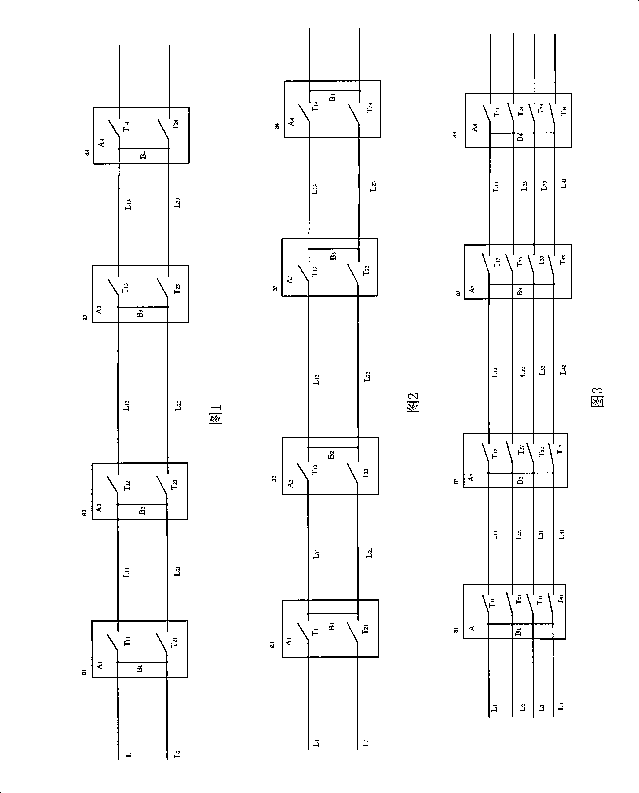
[0022] As shown in FIG. 1 , in this embodiment, the high-voltage power transmission system has two split conductors in the same phase or pole.
[0023] This embodiment includes two split wires L of the same phase or same polarity 1 and L 2 , from the direction of power supply to the power consumer, in the area where ice is frequently encountered along the transmission line, split the line L at intervals (about 50 kilometers) 1 and L 2 A disconnection point is set on it, so the entire split wire will be divided into several sub-sections by multiple disconnection points on it. A switch device is connected in series at each disconnection point of the transmission conductor, each switch device comprises two switches, and each switch is respectively connected between two adjacent subsections of different split conductors at the same disconnection point; and Split wire L 1 and L 2 The disconnection points of the same subsection are connected together by connecting lines. Figur...
Embodiment 2
[0029] As shown in FIG. 2 , the structure and principle of this embodiment are basically the same as those of Embodiment 1, and the transmission wires of the high-voltage power transmission system have two split wires of the same phase or same polarity. The difference is that the connecting wire is set on the output terminal of the switch. When needed at break point a 2 and break point a 3 When the ice-melting treatment is performed between the split conductor sub-sections, a 2 -a 3 Segment Split Wire L 12 and L 22 Current switching is to pass through the switch T of the next switching device from the power supply direction to the power consumer. 13 , T 23 Come take control.
Embodiment 3
[0031] As shown in FIG. 3, the present embodiment has four split conductors in the same phase or polarity.
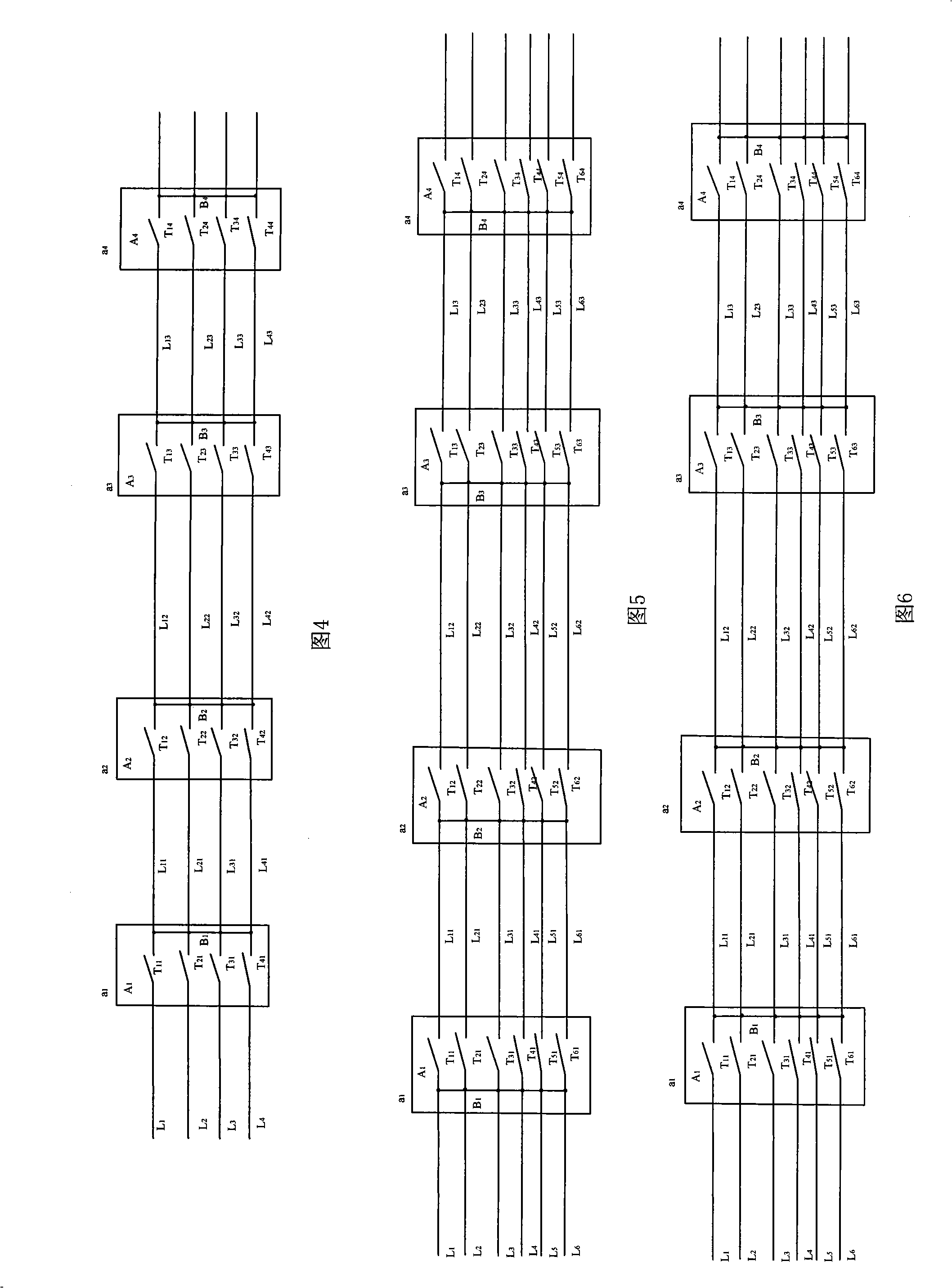
[0032] This embodiment is similar to Embodiment 1, the difference is that there are four split wires, correspondingly each switch device connected in series at each disconnection point of the power transmission wire has four switches, and each switch is connected in series in different split wires respectively. Between two adjacent subsections of the wire. And the input terminals of the four switches on each switch device are connected together through connecting wires.
[0033] The deicing principle of the present embodiment is as follows:
[0034] In an AC transmission system, the load current of each phase is designed to be 1500A, and a 4×400mm 2 The 4-split wires are used for power transmission, that is, the current of each wire is 375 amps. Through experiments, in a certain power transmission environment, the ice-melting current of the wire is 800 amps. When on...
PUM
 Abstract
Description
Claims
Application Information
 - Generate Ideas
- Intellectual Property
- Life Sciences
- Materials
- Tech Scout
- Unparalleled Data Quality
- Higher Quality Content
- 60% Fewer Hallucinations
Browse by: Latest US Patents, China's latest patents, Technical Efficacy Thesaurus, Application Domain, Technology Topic, Popular Technical Reports.
© 2025 PatSnap. All rights reserved.Legal|Privacy policy|Modern Slavery Act Transparency Statement|Sitemap|About US| Contact US: help@patsnap.com


