
A catenary deicing system

A catenary and contact line technology, applied in the installation of electric components, electromechanical devices, cables, etc., can solve the problems of increasing the load of the catenary, inconvenient operation, threatening the safe running of trains, etc., to reduce labor intensity and increase safety. Effect

Active Publication Date: 2022-03-22
EAST CHINA JIAOTONG UNIVERSITY
View PDF0 Cites 0 Cited by
  • Summary
  • Abstract
  • Description
  • Claims
  • Application Information

AI Technical Summary

Problems solved by technology

Moreover, the environment in which electrified railways are located is very harsh, and under the action of strong winds, the bearing load of the catenary is greatly increased
When the load on the catenary exceeds the design standard, the catenary may break due to excessive tension of the wires, threatening the safe running of the train
In addition, the icing of the catenary will also reduce the conductivity of the pantograph when it is in contact with the current, which will cause arcing of the catenary, and eventually burn the pantograph and the contact wire
However, the icing of catenary will also cause the phenomenon of bowing, which will damage the pantograph.
[0003] In the past, people usually used the mechanical deicing method, that is, manually knocking on the catenary, so that the basic net was forced to vibrate, so that the ice fell off.
However, this deicing effect is not ideal, which increases the labor intensity of the staff, and may cause certain damage to the catenary
However, the existing high-current ice-melting method needs to waste a large amount of electric energy and is inconvenient to operate; the AC-DC short-circuit ice-melting must first cut off the normal power transmission of the catenary in a short time, and if the control is not good, the contact line will be damaged; Ice will generate high-frequency electromagnetic waves, thereby interfering with the normal communication of other electrical equipment

Method used


Image

  • A catenary deicing system
  • A catenary deicing system
  • A catenary deicing system

Examples


Embodiment Construction

[0027] The present invention will be described in further detail below in conjunction with the embodiments and with reference to the accompanying drawings.

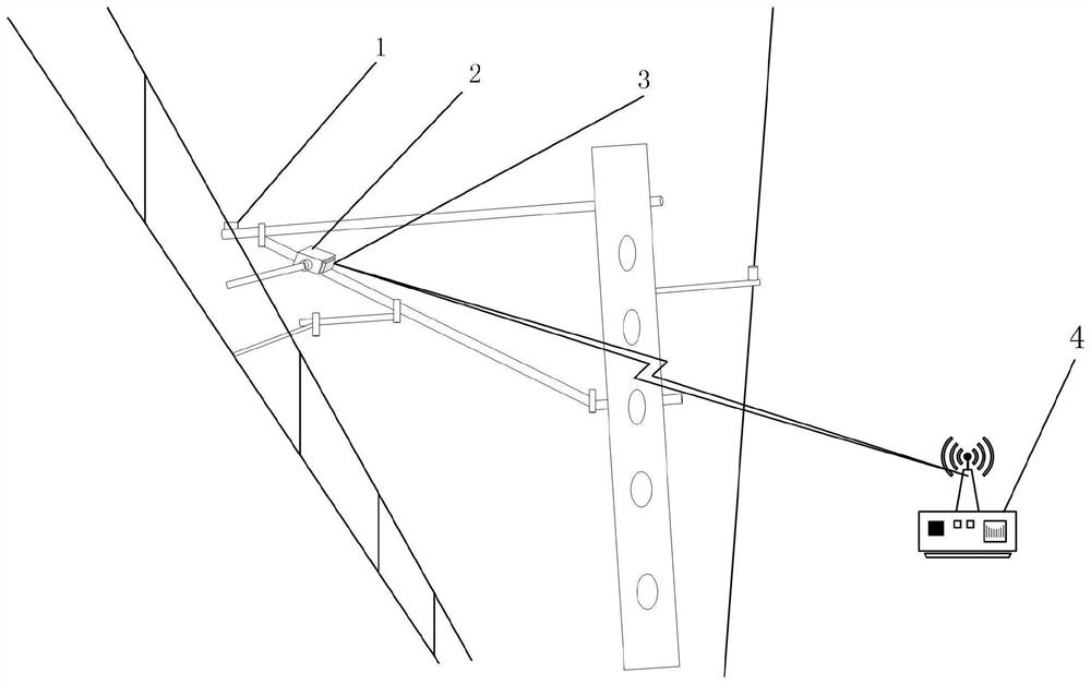
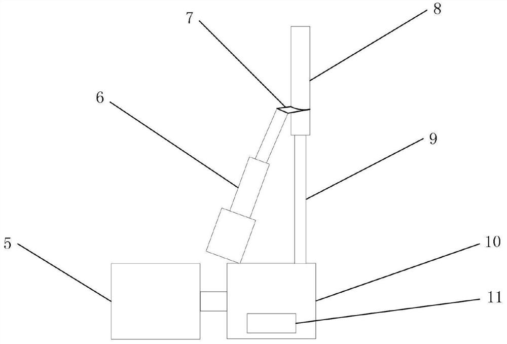
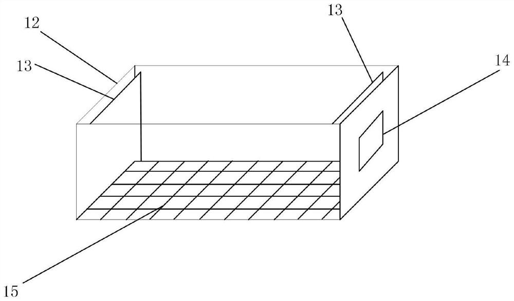
[0028] see Figure 1 to Figure 8 Shown is a catenary deicing system in the present invention, including an icing sensor 1 , a deicing machine 2 , a control circuit board 3 , and a converging node 4 .

[0029] Such as figure 1 As shown, the icing sensor 1 is installed at the position where the catenary cable is connected with the horizontal pull rod, and is used to detect the icing of the catenary. Cable deicing, the control circuit board 3 is installed next to the deicing machine 2, and is used to receive the information collected by the icing sensor 1 and the instruction information sent by the railway dispatching center, and control the deicing machine 2 to work according to the instruction information. A converging node 4 is set next to the network, which is used to gather the information collected by the icing senso...


PUM


Abstract

The invention discloses a catenary deicing system, which includes an icing sensor, a deicing machine, a control circuit board, and a converging node. The icing sensor is installed at the position where the catenary cable is connected with the horizontal pull rod, and is used for detecting icing of the catenary In some cases, the de-icing machine is installed on the wrist arm to de-ice the contact wire or catenary cable, and the control circuit board is installed next to the de-icing machine to receive the information collected by the icing sensor and the railway dispatching center. command information, and control the work of the deicing machine according to the command information. A converging node is set up next to the catenary to gather the information collected by the icing sensors in the line interval, and transmit the information to the railway dispatching center, which is dispatched by the railway The center sends deicing instructions to the deicing machine, controls the deicing machine to apply vibration to the contact wire or catenary wire, and forces the ice coating to fall through the vibration mechanical wave transmitted to the contact wire or catenary wire.

Description

technical field [0001] The invention relates to the field of catenary deicing, in particular to a catenary deicing system. Background technique [0002] With the rapid development of modern science and technology, my country's electrified railway construction has achieved leapfrog development. At present, the railway department attaches great importance to the safe operation of electrified railways. Icing accidents often occur on the catenary of electrified railways in my country, which has a very bad impact on the rapid development of electrified railways, especially in cold winters. When there are no trains passing by the railway for a long time, the catenary is easily surrounded by ice. This may make it difficult for the pantograph to obtain power, which poses a threat to the safe operation of the train. After the catenary is iced, the catenary equipment not only bears its own weight, but also bears the pressure brought by the ice. Moreover, the environment in which the...

Claims


Application Information

Patent Timeline
Patent Type & Authority Patents(China)
IPC IPC(8): H02G7/16H02J13/00H02K7/06G01D5/24
CPCH02G7/16H02J13/00022H02K7/06G01D5/24
Inventor 胡军刘燕德吴梦飞郇海瑶贾军昊罗搏一
Owner EAST CHINA JIAOTONG UNIVERSITY
Learn More