
High performance fuel heat accumulation type condensation energy-saving boiler

A regenerative, high calorific value technology, applied in steam boilers, cylinder steam boilers, combustion methods, etc., can solve the problems of uneven temperature distribution in the combustion chamber, affecting the life of the furnace body, and high exhaust gas temperature, so as to eliminate local high temperature zone, reduce heat energy loss, and increase the effect of combustion temperature

Inactive Publication Date: 2010-05-26
SHENWU TECH GRP CO LTD
View PDF3 Cites 2 Cited by
  • Summary
  • Abstract
  • Description
  • Claims
  • Application Information

AI Technical Summary

Problems solved by technology

[0004] The above-mentioned prior art has at least the following disadvantages: firstly, when the calorific value of the fuel is the same, the temperature in the combustion chamber is low due to the low-temperature air combustion, and the temperature distribution in the combustion chamber is uneven, and there are local high-temperature areas, which affect the life of the furnace body; secondly, The exhaust gas temperature is high, taking away a lot of heat energy, and the combustion efficiency is low

Method used


Image

  • High performance fuel heat accumulation type condensation energy-saving boiler
  • High performance fuel heat accumulation type condensation energy-saving boiler
  • High performance fuel heat accumulation type condensation energy-saving boiler

Examples


Embodiment Construction

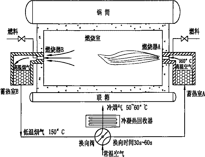
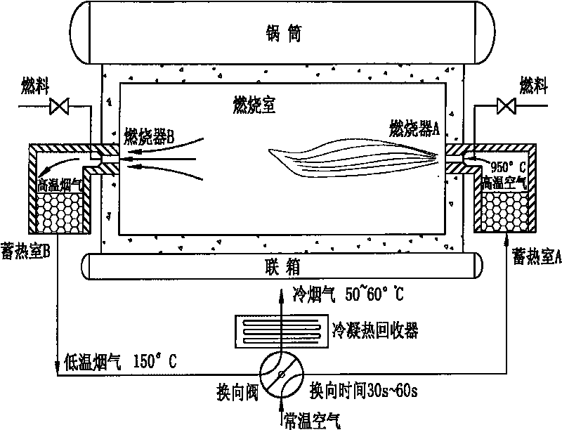
[0011] The preferred specific implementation of the high calorific value fuel regenerative condensing energy-saving boiler of the present invention is as follows figure 2 As shown, including the furnace body, the interior of the furnace body constitutes a combustion chamber, and burners are installed on the wall of the furnace body. The furnace body is equipped with at least two burners, and multiple burners can be provided. Among the plurality of burners, every two burners are a pair, and the burners are periodically switched to each other. 1, 2, 3, 4 pairs of burners can be set, and other numbers can also be used as required.

[0012] The burner is provided with a high-temperature combustion-supporting air inlet and a fuel inlet, wherein the high-temperature combustion-supporting air inlet is used as a high-temperature flue gas outlet when the burner stops burning. Specifically, when the burner is burning, the high-temperature combustion-supporting air inlet is used to ent...


PUM


Abstract

The invention discloses a heat accumulating type condensing and energy saving boiler for high energy fuel, which comprises a boiler body. Two or more combustors are arranged in the boiler body, a high-temperature combustion-supporting air inlet opening and a fuel spraying opening are arranged on the combustor, a checker chamber is connected with the high-temperature combustion-supporting air inletopening, a normal temperature combustion-supporting air inlet and a low-temperature flue gas outlet are connected with the checker chamber, a direction change device is arranged between the normal temperature combustion-supporting air inlet and the low-temperature flue gas outlet, and a condensing heat recoverer is connected with the low-temperature flue gas outlet. On one hand, when the fuel gasis discharged, the waste heat of the fuel gas is recovered through the checker chamber and the condensing heat recoverer, thereby the heat energy loss is reduced, and the combustion efficiency is enhanced; on the other hand, after passing through the checker chamber, the normal temperature combustion-supporting air assists in combustion supporting, and thereby the combustion temperature can be increased; thirdly, a plurality of combustors adopts periodic reversing combustion, thereby the partial high temperature zones in the combustors are avoided, and the internal temperature distribution ofthe combustors is more uniform. The boiler is applied to various gas fired boilers.

Description

technical field [0001] The invention relates to a steam generating device, in particular to a boiler. Background technique [0002] Boilers are commonly used steam generating devices, but the existing boilers generally have low combustion efficiency and high combustion costs. [0003] Such as figure 1 Shown is a structural schematic diagram of a boiler in the prior art. The interior of the furnace body constitutes a combustion chamber, and a burner is installed on one side of the furnace body; aisle. Combustion-supporting air at room temperature is mixed with fuel and burned in the combustion chamber, and the hot flue gas after combustion is discharged out of the combustion chamber through the hot flue gas discharge channel. [0004] The above-mentioned prior art has at least the following disadvantages: first, when the calorific value of the fuel is the same, low-temperature air supports combustion, the temperature in the combustion chamber is relatively low, and the tem...

Claims


Application Information

Patent Timeline
Patent Type & Authority Patents(China)
IPC IPC(8): F23L15/00F22B5/04
CPCY02E20/34
Inventor 吴道洪胡韬王正华王东方阮立明
Owner SHENWU TECH GRP CO LTD
Learn More