Garbage incinerator with whirlpool arch and thermal island

A waste incinerator and vortex technology, applied in the direction of incinerator, combustion method, combustion type, etc., can solve the problems of insufficient mixing and combustion of flue gas, short residence time of flue gas, high manufacturing cost, etc. Extended life, good ventilation effect

Inactive Publication Date: 2008-12-10
朴显泽 +2
View PDF0 Cites 3 Cited by
  • Summary
  • Abstract
  • Description
  • Claims
  • Application Information

AI Technical Summary

Problems solved by technology

[0002] At present, domestic and foreign waste incineration boilers mostly use fluidized bed or reciprocating boilers. For example, the "Introduction to 160t Daily Waste Incineration Boiler" published in the fifth issue of "Industrial Boiler" in 2006 disclosed the research and development of Wuxi Huaguang Boiler Co., Ltd. A kind of waste incineration boiler produced, the waste incineration boiler adopts reverse push reciprocating grate, the structure is similar to the coal-fired reciprocating furnace, the fuel communicates with the furnace, and the secondary air is arranged between the throats of the front and rear arches of the furnace. The structure can play a certain role in supplementing oxygen and preventing carbon black particles from falling back to the fire grate for combustion, but the residence time of the flue gas in the combustion chamber is short, and the flue gas cannot be fully mixed and burned. In order to prolong the residence time of the flue gas in the combustion chamber, The waste incineration boiler has a relatively high furnace body, with a daily processing capacity of 160t and a rated evaporation capacity of 10T / h. The furnace body is as high as 27.5 meters, which takes up a lot of space and high manufacturing costs

Method used


Image

  • Garbage incinerator with whirlpool arch and thermal island
  • Garbage incinerator with whirlpool arch and thermal island
  • Garbage incinerator with whirlpool arch and thermal island

Examples


Embodiment Construction

[0012] The present invention will be further described below in conjunction with accompanying drawing:

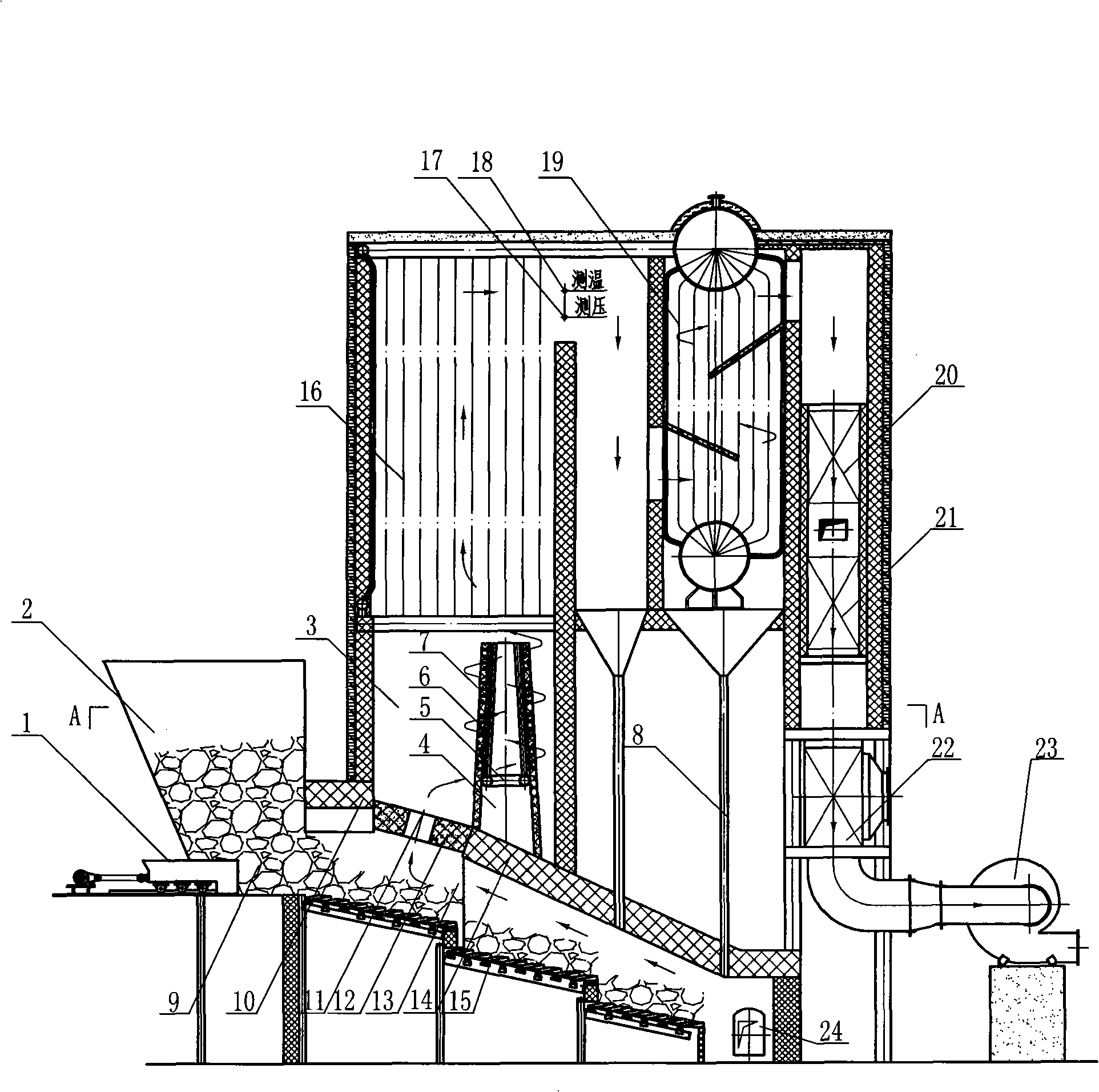
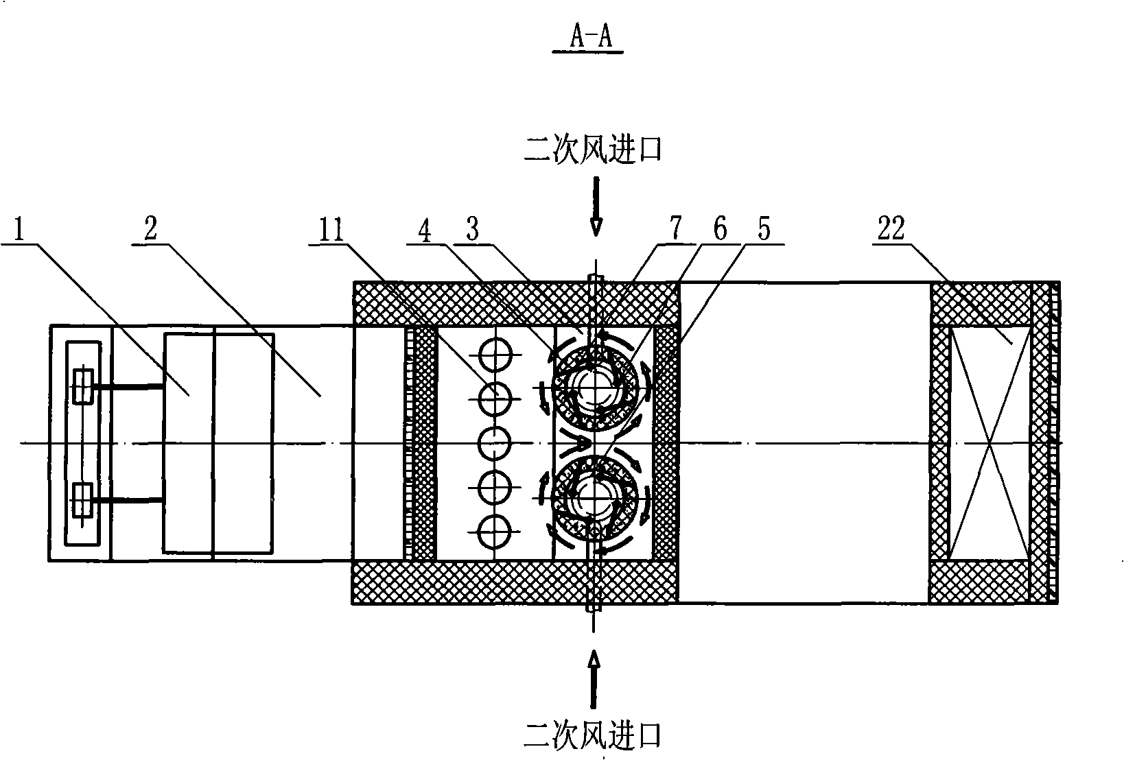
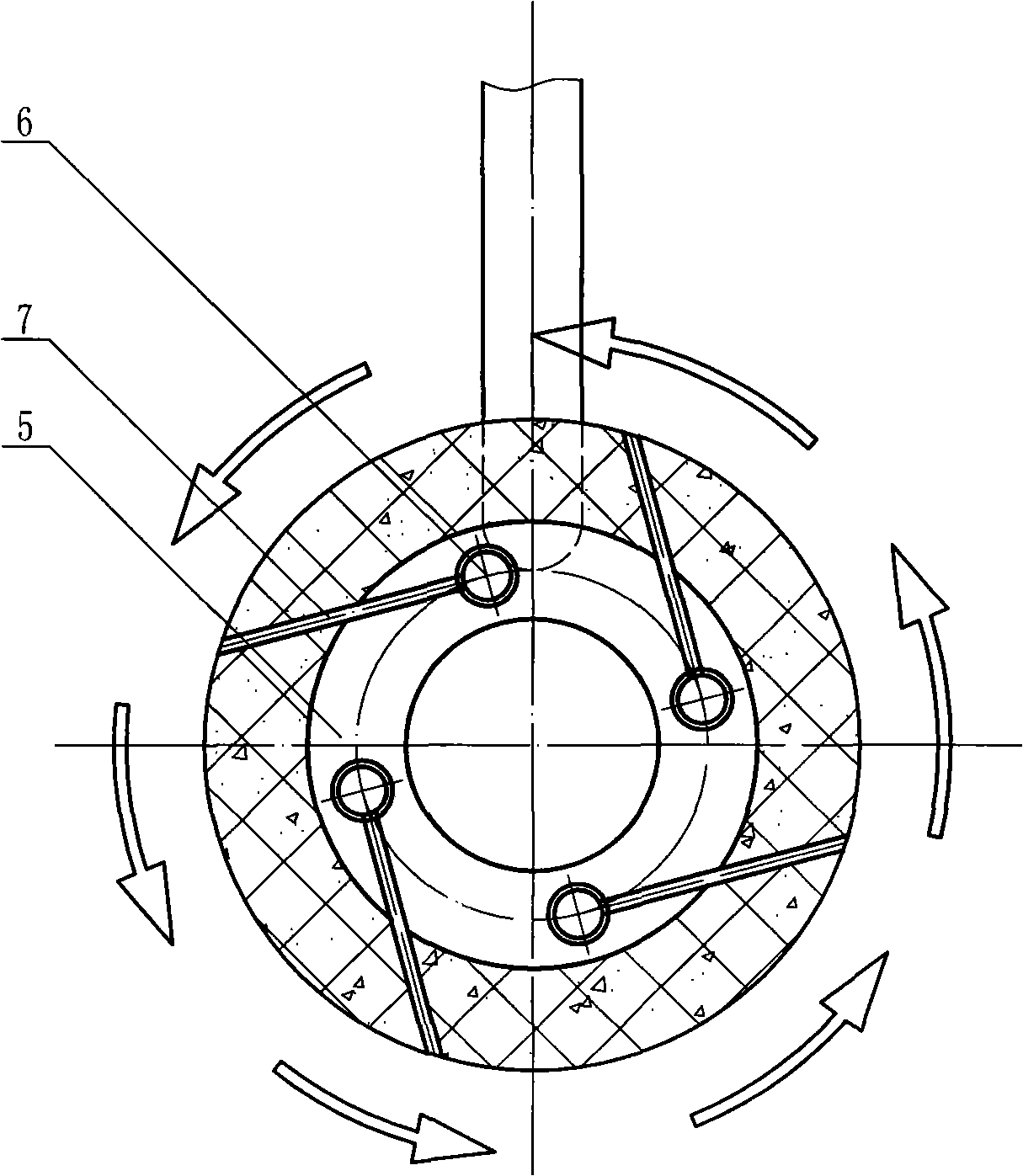
[0013] Such as figure 1 and figure 2 Shown: the present invention mainly comprises, reciprocating furnace body, difference is: a vortex arch 12 is built between the throat of front arch 10 and back arch 14 of furnace hearth, furnace hearth is divided into two chambers, and upper chamber is for burning Chamber 3, the lower chamber is a cracking chamber 13; five vortex holes 11 are arranged on the vortex arch, and the cracking chamber 13 communicates with the combustion chamber 3 through the vortex holes 11; it is set above the rear arch 14 in the combustion chamber 3 2 garden-shaped heat islands 4 with a diameter of 1500 mm and a height of 3000 mm. The heat islands 4 can be prefabricated with refractory mixed soil, or can be processed into ceramic products. The heat insulation arrangement and the installation position can be adjusted at will; the patent application number ...


PUM


Abstract

The invention discloses a garbage furnace with a vortex arch and a heat island, which aims at providing a garbage furnace which can ensure the staying time of the flue gas in a combustion chamber to be prolonged, the flue gas to be adequately mixed and burnt, the secondary pollution to be avoided, and simultaneously the height of the furnace body and the manufacturing cost to be reduced. The garbage furnace comprises a reciprocating furnace body, a vortex arch (12) with a vortex hole (11) is arranged between the throat opening of a front arch (10) and a rear arch (14) of a hearth, a combustion chamber (3) is arranged at the upper part of the vortex arch (12), a cracking chamber (13) is arranged at the lower part, and the combustion chamber (3) is mutually communicated with the cracking chamber (13) through the vortex hole (11); a reciprocating grate (15) with the head supplying air is arranged at the lower part of the cracking chamber (13); a heat island (4) is arranged at the upper part of the rear arch (14) in the combustion chamber (3), and a multilevel and multi-row vortex secondary air system distributed in the tangential direction of a secondary air main pipe (5) is arranged in the heat island (4); the garbage furnace is applied to the domestic garbage disposal, and the generated heat can be applied to the power generation, the heating and other industrial gas.

Description

technical field [0001] The invention relates to a garbage incineration device, in particular to a boiler for burning garbage Background technique [0002] At present, domestic and foreign waste incineration boilers mostly use fluidized bed or reciprocating boilers. For example, "Introduction to 160t Daily Waste Incineration Boiler" published in the fifth issue of "Industrial Boiler" in 2006 disclosed the research and development of Wuxi Huaguang Boiler Co., Ltd. A kind of waste incineration boiler produced, the waste incineration boiler adopts the reverse push reciprocating grate, the structure is similar to the coal-fired reciprocating furnace, the fuel communicates with the furnace, and the secondary air is arranged between the throats of the front and rear arches of the furnace. The structure can play a certain role in supplementing oxygen and preventing carbon black particles from falling back to the fire grate for combustion, but the residence time of the flue gas in th...

Claims


Application Information

Patent Timeline
Patent Type & Authority Applications(China)
IPC IPC(8): F23G5/44F23G5/28
Inventor 朴显泽马建华
Owner 朴显泽
Why Eureka
Try Eureka