Duplexed LED point type light source colour lamp signal machine control circuit

A technology for controlling circuits and point light sources, which is applied to the layout of electric lamp circuits, light sources, electric light sources, etc. It can solve the problems that the detection method is susceptible to external interference and the LED light source cannot be powered by constant current, so as to ensure brightness and spectrum, and ensure reliability. performance, ensuring a stable effect

Inactive Publication Date: 2013-09-25
INST OF SCI & TECH SHANGHAI RAILWAYBUREAU
View PDF1 Cites 2 Cited by
  • Summary
  • Abstract
  • Description
  • Claims
  • Application Information

AI Technical Summary

Problems solved by technology

However, this technical solution uses photoresistors for LED open and short circuit detection. This detection method is susceptible to external interference and has hidden dangers. In addition, the LED light source cannot be powered by a constant current, and the constant current power supply is important for ensuring the brightness and spectrum of the LED. Stability is very important; moreover, this technical solution still needs to transform the original power transformer

Method used


Image

  • Duplexed LED point type light source colour lamp signal machine control circuit
  • Duplexed LED point type light source colour lamp signal machine control circuit

Examples


Embodiment Construction

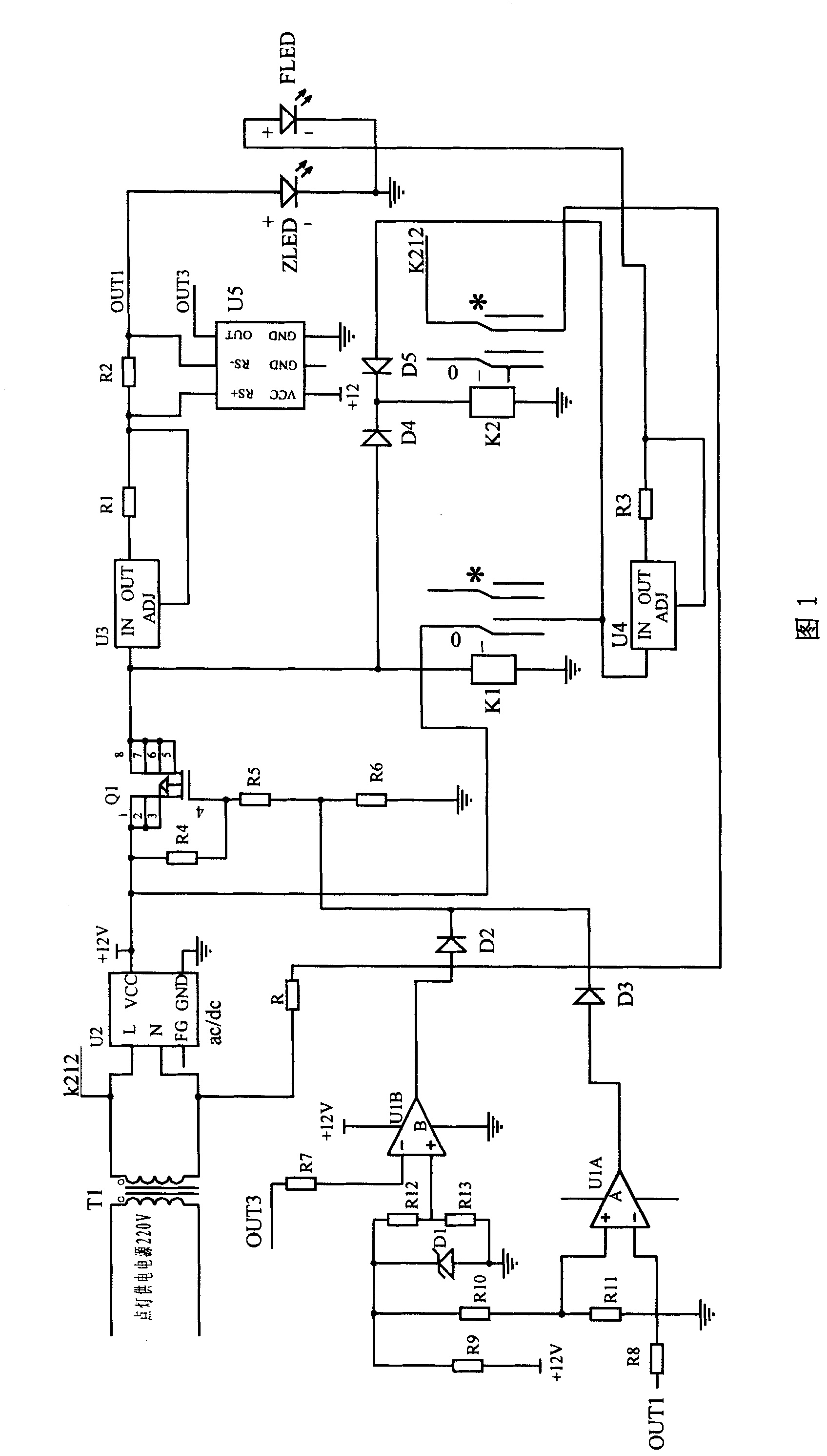
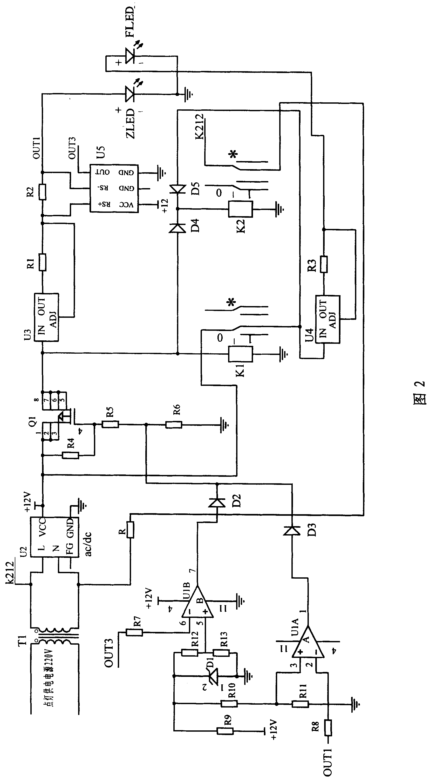
[0050] See attached figure 1, from the railway signal building lighting power supply AC 220V, the power supply is connected to the primary side of the lighting transformer T1, after first stepping down by T1, the secondary side of the lighting transformer T1 outputs AC 13V power. One end of the lighting transformer current matcher R is directly connected to one end of the secondary AC output of the lighting transformer T1, and the other end is connected to the other end of the secondary AC output of the lighting transformer T1 through the normally open contact "K212" of the lighting status relay K2. The secondary output AC 13V power supply of the lighting transformer T1 is connected to the "L" and "N" terminals of the power module U2, and the power module U2 converts the AC 13V into a DC 12V output. The DC 12V positive pole is connected to one end (pins 1, 2, and 3) of the switch MOS transistor Q1. The other end (pins 5, 6, 7, and 8) of the switching MOS transistor Q1 is conn...


PUM


Abstract

The invention relates to a control circuit that is used in a double LED pointolite color light signal and comprises a lighting control part, a failure testing part and a power supply part. The control circuit also comprises an LED main light source loop and an LED auxiliary light source loop which are respectively composed of the three parts. A lighting transformer is secondarily connected in parallel with a current matcher of the lighting transformer, thus causing the primary current value to reach the rated range which ensures that a filament relay can work normally. The control circuit adopts constant current power supply so as to eliminate the influence on the current value of the LED loops caused by voltage fluctuation. A current detecting chip and a current sampling resistance are adopted and connected in parallel so as to form a detection unit which is connected in series to the LED main light source loop, and the anode of the LED main light source loop is taken as a voltage detecting point. When open circuit or short circuit occurs to the LED main light source loop, the output value of a detecting circuit changes accordingly and controls the output state of a comparator, thus further controlling opening or closing a switch MOS conduit in the loop and realizing the switch between a main light source and an auxiliary light source and failure warning. When railway signal lamps are replaced by the LED, the existing circuit equipment are not necessary to be changed, which ensures the reliability of a signal interlocking circuit.

Description

technical field [0001] The invention relates to a railway colored light signal machine and its lighting control circuit, in particular to the monitoring and control of a double-set dot type railway colored light signal machine made of high-power LED light emitting devices. technical background [0002] For a long time, railway signal lights have used incandescent lamps as signal light sources. In the power supply circuit of the incandescent signal machine, there is a filament relay in series to monitor the working state of the filament. Its function is to detect the current flowing into the signal machine. Only when the current flowing into the signal machine is normal, the filament relay can be closed. Closed means that the signal machine is working normally. Filament relays have been used in railway signaling systems for decades, and they are established products with reliable performance. In recent years, color light signals using LEDs as light sources are gradually rep...

Claims


Application Information

Patent Timeline
Patent Type & Authority Patents(China)
IPC IPC(8): G05F1/46H05B37/02
Inventor 王正权张海南葛明钧
Owner INST OF SCI & TECH SHANGHAI RAILWAYBUREAU
Why Eureka
Try Eureka