
Sliding closure structure of portable electronic device

An electronic device and portable technology, applied in the direction of telephone structure, telephone communication, electrical components, etc., can solve problems such as damage to electrical connectors 93, and achieve the effect of avoiding friction and high strength

Inactive Publication Date: 2008-12-03
SHENZHEN FUTAIHONG PRECISION IND CO LTD +1
View PDF0 Cites 10 Cited by
  • Summary
  • Abstract
  • Description
  • Claims
  • Application Information

AI Technical Summary

Problems solved by technology

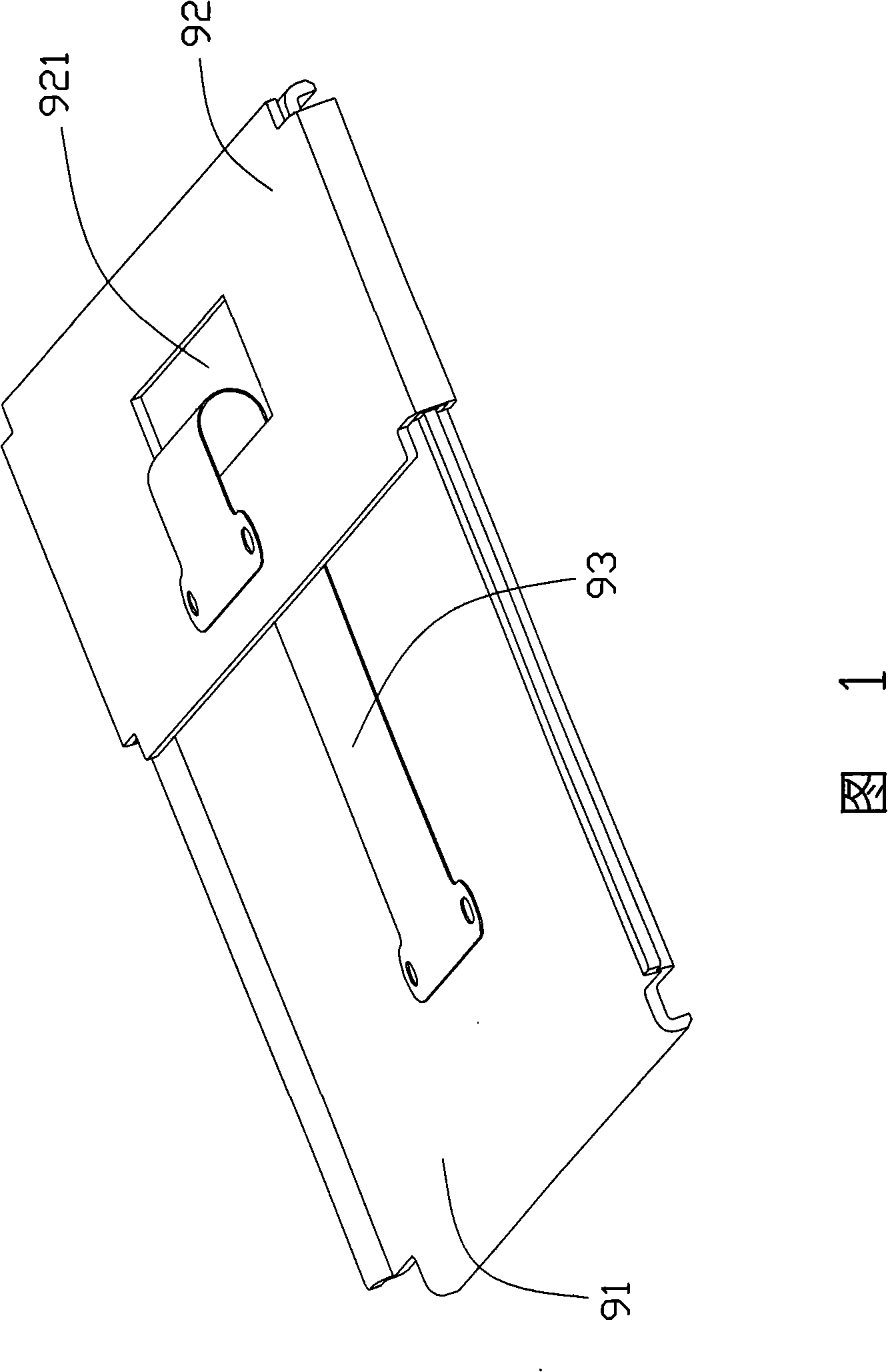
If the through hole 921 is opened smaller, the movement of the electrical connector 93 may be restricted during the sliding process, and the edge of the through hole 921 may scratch with the electrical connector 93 to damage the electrical connector. 93

Method used


Image

  • Sliding closure structure of portable electronic device
  • Sliding closure structure of portable electronic device
  • Sliding closure structure of portable electronic device

Examples


Embodiment Construction

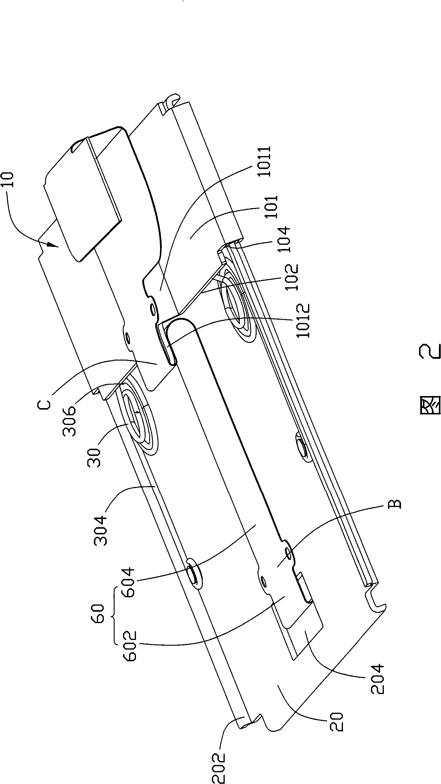
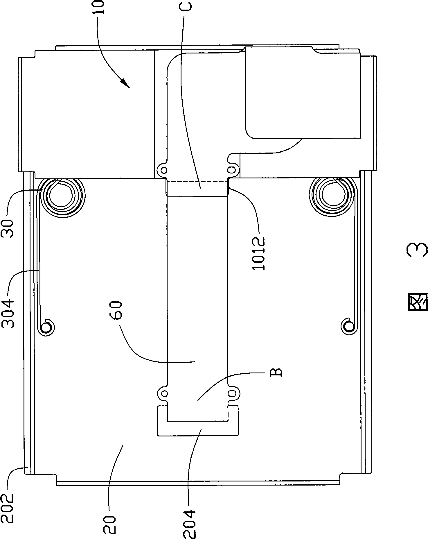
[0016] Please refer to Fig. 2 to Fig. 4, the preferred embodiment of the slide cover structure of the present invention is used in a slide cover type portable electronic device, and this slide cover type portable electronic device can be mobile phone, game machine, personal digital assistant (Personal digital assistant) assistant, PDA) and so on. The sliding cover type portable electronic device includes a body (not shown in the figure) and a cover (not shown in the figure), and the cover is reciprocally and slidably mounted on the body.

[0017] A preferred embodiment of the sliding cover structure of the present invention includes a fixing part 10 , a sliding part 20 , two restoring mechanisms 30 and an electrical connecting part 60 . The sliding part 20 is installed on the fixing part 10 , can move back and forth along the path defined by the fixing part 10 , and can automatically return to the initial position driven by the restoring mechanism 30 . The electrical connecto...


PUM


Abstract

The invention provides a sliding closure structure applied to a sliding closure typed portable electronic device, comprising a fixed part, a sliding part and an electric connecting part. The fixed part comprises a containing part; the sliding part can be movably arranged on the fixed part. Two ends of the electric connecting part are fixedly arranged on the fixed part and the sliding part respectively; when the sliding part moves correspondingly to the fixed part, the electric connecting part is partly contained inside the containing part.

Description

technical field [0001] The invention relates to a sliding cover structure of a portable electronic device, in particular to a sliding cover structure of a portable electronic device which is beneficial to improving the overall structural strength and facilitating the movement of the cover body. Background technique [0002] A large part of portable electronic devices adopts a sliding cover structure. Please refer to FIG. 1 , the existing sliding cover structure includes a fixing part 91 and a sliding part 92 . Both the fixing part 91 and the sliding part 92 are roughly rectangular in shape, and the two ends of the sliding part 92 are respectively bent inwards into a hook shape and then put on two opposite edges of the fixing part 91, so that the sliding part 92 can be placed on the Slide back and forth on the fixing part 91. A rectangular through hole 921 is defined in a central portion of the sliding member 92 . [0003] During assembly, the fixing part 91 and the slidin...

Claims


Application Information

Patent Timeline
Patent Type & Authority Applications(China)
IPC IPC(8): H04B1/03H04B1/08H04M1/02H04B1/38
CPCH04M1/0237H04M1/0274
Inventor 张正龙曹美足陈丙洲
Owner SHENZHEN FUTAIHONG PRECISION IND CO LTD
Learn More