Roller conveying apparatus with solid-liquid separation function
A conveying device and a solid-liquid separation technology, which is applied in packaging and other directions, can solve the problems of not being able to transport slag, not having the function of solid-liquid separation, and expanding the amount of feed, so as to improve performance, run without jamming, and run smoothly. smooth effect
Active Publication Date: 2010-12-01
BAOSHAN IRON & STEEL CO LTD
View PDF1 Cites 0 Cited by
- Summary
- Abstract
- Description
- Claims
- Application Information
AI Technical Summary
Problems solved by technology
This invention is mainly used for conveying powder, which is to enlarge its feeding amount, and cannot be used for conveying the solid-liquid mixed slag discharged from the roller method device, nor does it have the function of solid-liquid separation
Method used
View moreImage
Smart ImageViewing Examples
Examples
Embodiment Construction
Login to View More PUM
 Abstract
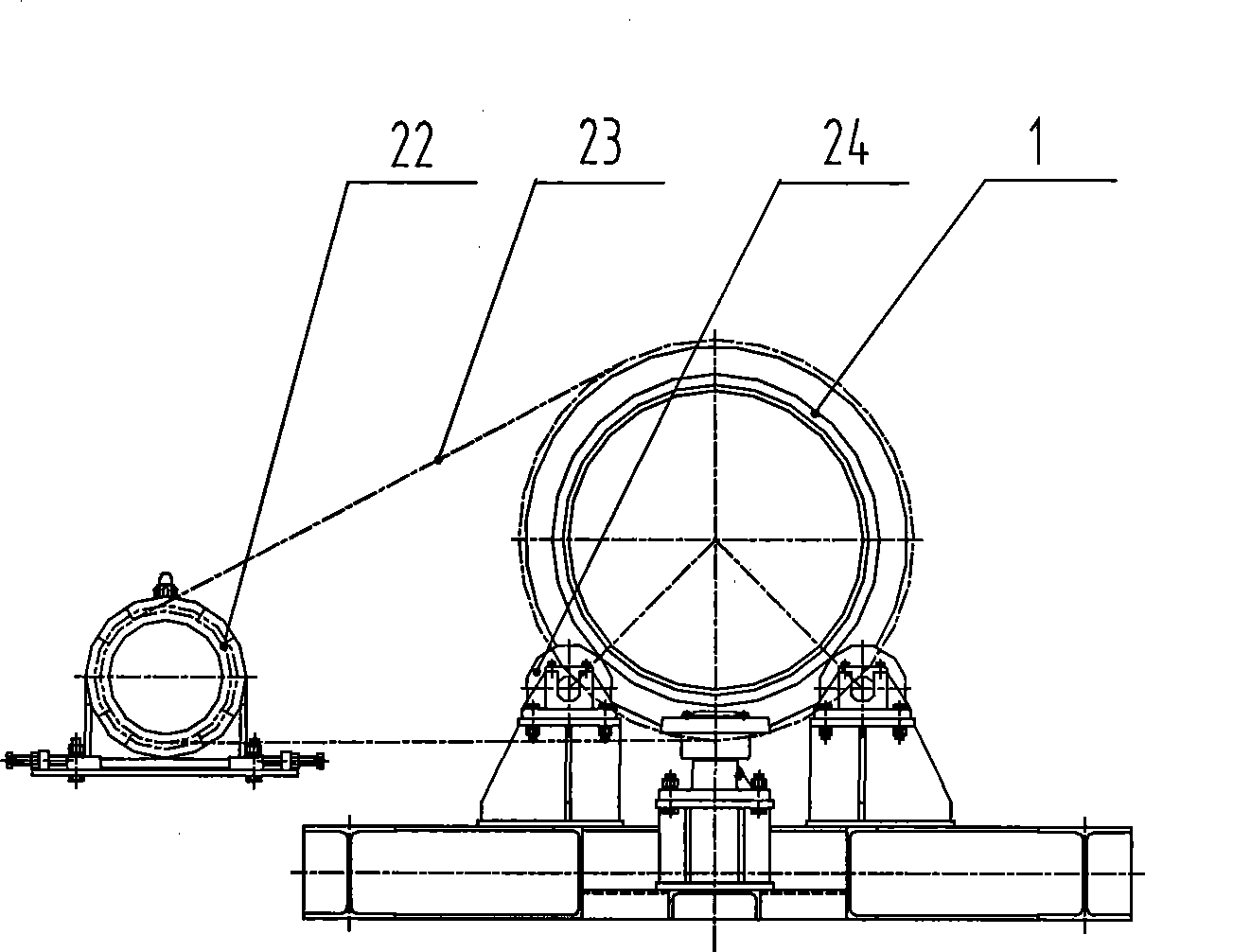
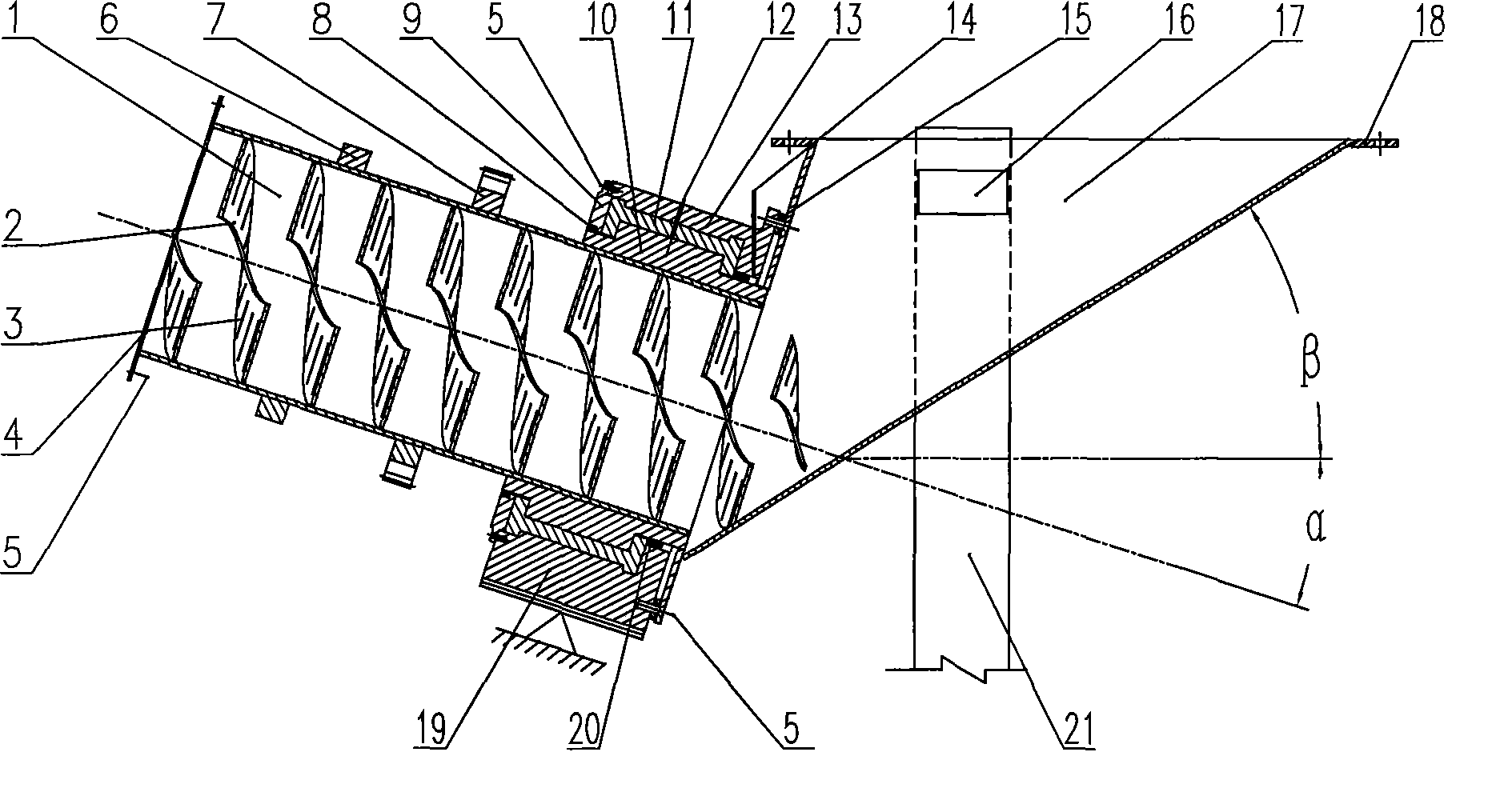
The invention relates to a roller conveyer device for metallurgical slag materials. The roller conveyer device with a solid-liquid separation function comprises an internal spiral roller, a feed funnel and a sealing-supporting device, wherein the sealing-supporting device connects the rotating internal spiral roller with the static feed funnel into a whole; the internal spiral roller and the feedfunnel are arranged in a V shape, and the internal spiral roller has an included angle with the horizontal plane; the periphery of the internal spiral roller is sleeved with a shaft sleeve capable ofrotating together with the internal spiral roller; the shaft sleeve is arranged inside the sealing-supporting device; the shaft sleeve is shaped like a Chinese character 'tu'; one end and the peripheral surface of the shaft sleeve are in sliding contact with the sealing-supporting device; one end of the sealing-supporting device is fixed with a discharge hole of the feed funnel; the roller is driven to rotate by a driving device; the inner wall of the roller is fixed with at least one continuous spiral blade. The roller conveyer device can convey solid particles to a certain height and realize solid-liquid separation, is good in sealing effect, and can eliminate steam overflow caused by materials.
Description
Roller conveying device with solid-liquid separation function technical field The invention relates to a roller conveying device for metallurgical slag. Background technique Compared with other metallurgical slag treatment technologies, the drum method metallurgical slag treatment technology has the advantages of short process, less investment, safety and reliability, low energy consumption, direct utilization of treated slag, and less pollution. It has been gradually recognized and rapidly promoted by the industry. For the transportation of the slag discharged from the drum device, the chain conveyor is currently used to transport the material to the slag yard. Since the discharge of the drum is a mixture of slag and water, a large amount of fine slag will flow from the chain conveyor along with the water. The flow out from the gap of the chain plate causes a large amount of slag accumulation in the lower part of the chain plate machine, which will not only bring a lot of...
Claims
Login to View More Application Information
Patent Timeline
 Patent Type & Authority Patents(China)
IPC IPC(8): B65G33/12
Inventor 肖永力刘茵
Owner BAOSHAN IRON & STEEL CO LTD
Features
- R&D
- Intellectual Property
- Life Sciences
- Materials
- Tech Scout
- Unparalleled Data Quality
- Higher Quality Content
- 60% Fewer Hallucinations
Learn More Browse by: Latest US Patents, China's latest patents, Technical Efficacy Thesaurus, Application Domain, Technology Topic, Popular Technical Reports.
© 2025 PatSnap. All rights reserved.Legal|Privacy policy|Modern Slavery Act Transparency Statement|Sitemap|About US| Contact US: help@patsnap.com


