
Positioning method for trunnion shaft assembly phase point

A positioning method and technology for balancing shafts, which are used in static/dynamic balance testing, measuring devices, and machine/structural component testing. reduced effect

Inactive Publication Date: 2008-12-03
CHONGQING JUCHENG MACHINERY
View PDF0 Cites 9 Cited by
  • Summary
  • Abstract
  • Description
  • Claims
  • Application Information

AI Technical Summary

Problems solved by technology

[0004] The problem to be solved by the present invention is to provide a positioning method for the assembly phase point of the balance shaft, so as to solve the problem that the traditional determination method causes errors in the position of the assembly phase point due to the casting process, manufacturing errors and uneven materials

Method used


Image

  • Positioning method for trunnion shaft assembly phase point
  • Positioning method for trunnion shaft assembly phase point
  • Positioning method for trunnion shaft assembly phase point

Examples


Embodiment 1

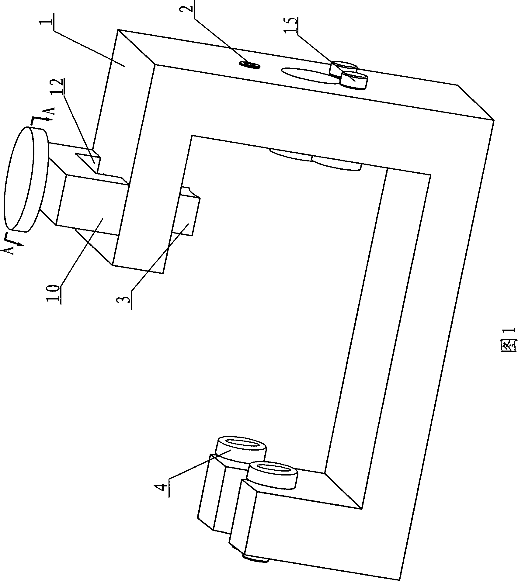
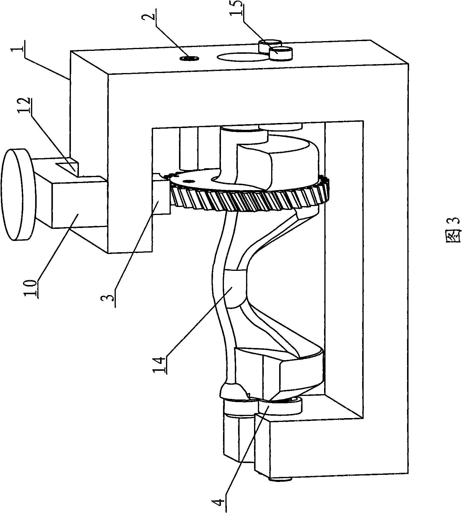
[0030] Embodiment 1, as shown in Figures 1 and 3, the supporting mechanism is two rolling bearings 4 arranged in parallel, and the two rolling bearings 4 are installed on the frame 1 through the shaft 15, and the distance between the two rolling bearings 4 is smaller than that of the journal end of the balance shaft 14. diameter. The journal ends of the balance shaft 14 are placed on the two rolling bearings 4 . The friction between the rolling bearing and the balance shaft 14 is relatively small, almost zero, and the counterweight on the balance shaft 14 is in a freely hanging state.

Embodiment 2

[0031] Embodiment 2, as shown in Figure 4, the support mechanism is a thimble structure, the thimble 7 is inserted in the thimble holes at both ends of the balance shaft 14 from the axial direction, the contact surface between the balance shaft 14 and the thimble is small, and the balance shaft 14 is supported on Free swing can be realized on the thimble, and the counterweight on the balance shaft 14 is in a freely hanging state during static balance.

Embodiment 3

[0032] Embodiment 3, as shown in FIG. 5 , the supporting mechanism is a V-shaped groove structure. Place the two ends of the balance shaft 14 in the V-shaped groove respectively. The two sides of the V-shaped groove 8 should be as smooth as possible. When the two ends of the balance shaft 14 are supported in the V-shaped groove 8, they can swing freely. The counterweight on the 14 is in free-hanging state.


PUM


Abstract

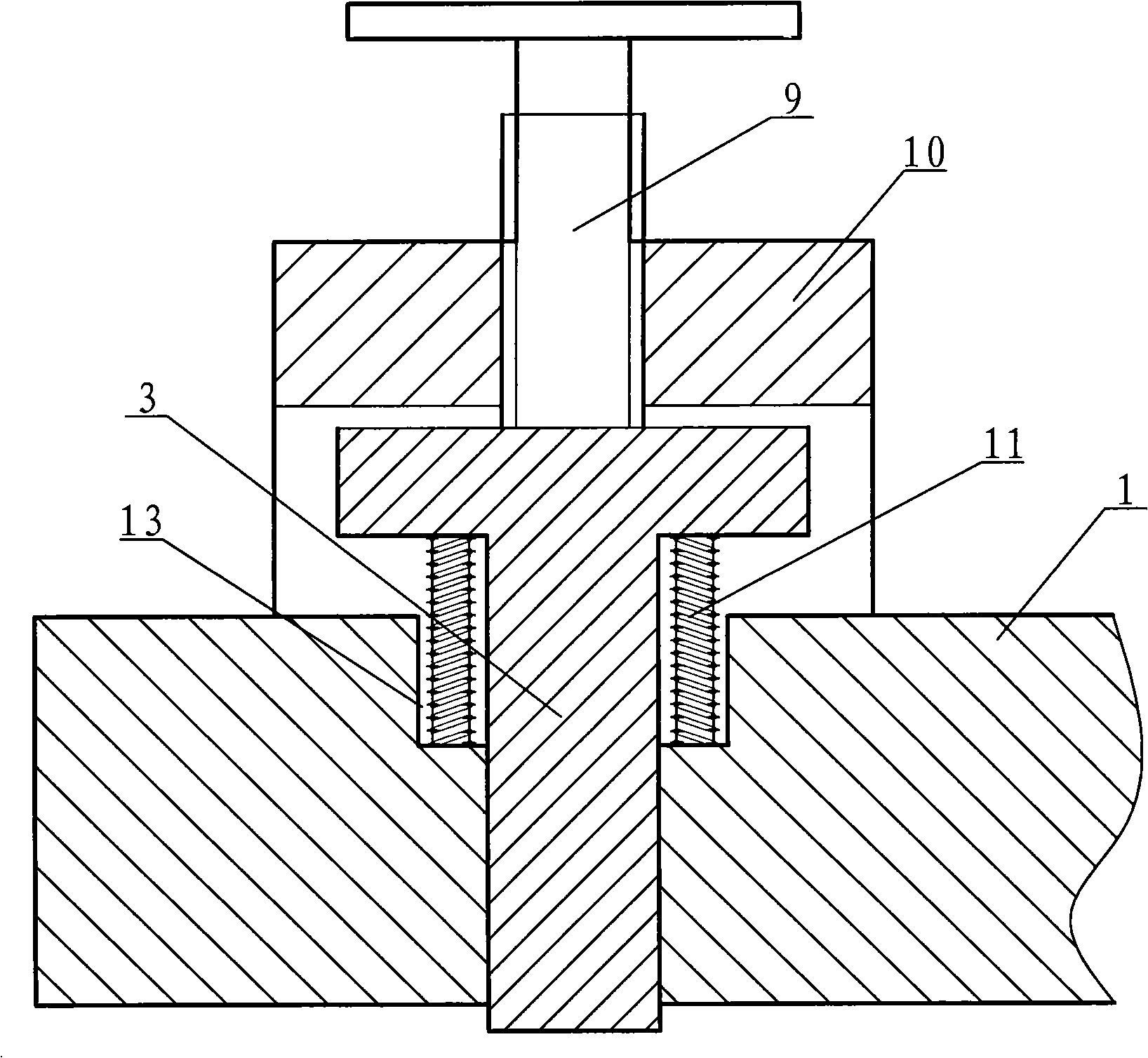
The invention relates to a method for positioning an assembly phase point of a balancing shaft. The method is characterized by comprising the following steps that: two ends of the balancing shaft are supported on special tool equipment in a laying mode in order that an axial lead of the balancing shaft is horizontal; a balance weight of the balancing shaft is positioned in a free overhanging state; when the balancing shaft is in static balancing, the balancing shaft is fixed; a process hole is processed on the upper part of the balance weight on the end face of a fluted disc of the balancing shaft in order that the process hole is positioned in a vertical plane which passes through the center of gravity of the balance weight; with an axial centre as a centre and the process hole as a benchmark, a marker is marked on a set angle position of the fluted disc end face of the balancing shaft in the clockwise direction or counterclockwise direction; and the marker is the assembly phase point of the balancing shaft. The assembly phase point of the balancing shaft determined by the method is not influenced by the foundry process, manufacturing error and uneven materials. The vibration of an engine after the balancing shaft is assembled is obviously reduced.

Description

technical field [0001] The invention relates to a processing technology of an engine balance shaft, in particular to a method for locating assembly phase points on the balance shaft during the processing of the balance shaft. Background technique [0002] The engine balance shaft is mainly used to balance the second-order inertial force of the engine, so as to reduce the vibration and noise of the whole engine. The balance shaft is directly driven by the crankshaft and has a strict phase relationship with the crankshaft. In order to make the phase between the crankshaft and the balance shaft meet the design requirements after the engine is assembled, corresponding marks must be marked on the main balance shaft and the tooth disc respectively during manufacture, which are called assembly phase points. The assembly phase points on the alignment. [0003] At present, in the machining process of the engine balance shaft, the balance shaft blank is usually cast first, then the ...

Claims


Application Information

Patent Timeline
IPC IPC(8): B23P19/00B23P19/10G01M1/12G01M1/02
Inventor 杜江
Owner CHONGQING JUCHENG MACHINERY
Learn More