
Semiconductor device and its grid and metal line forming method

A metal circuit pattern and semiconductor technology, which is applied in semiconductor devices, semiconductor/solid-state device manufacturing, circuits, etc., can solve the problem that the electrical characteristics of MOS transistors are different from expected values, etc.

Inactive Publication Date: 2008-11-26
SK HYNIX INC
View PDF0 Cites 7 Cited by
  • Summary
  • Abstract
  • Description
  • Claims
  • Application Information

AI Technical Summary

Problems solved by technology

However, in terms of circuit structure, the channel lengths of MOS transistors can only be different from each other. Therefore, as shown in FIG. MOS transistors have different electrical characteristics than expected

Method used


Image

  • Semiconductor device and its grid and metal line forming method
  • Semiconductor device and its grid and metal line forming method
  • Semiconductor device and its grid and metal line forming method

Examples


Embodiment Construction

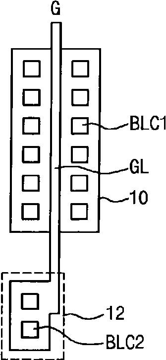
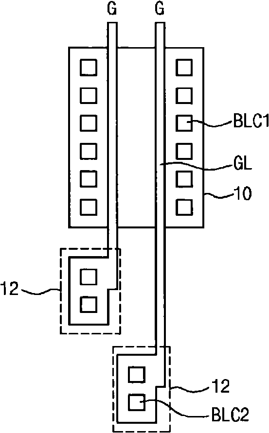
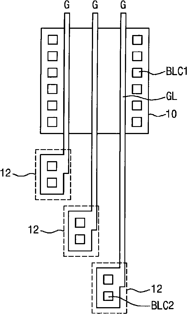
The semiconductor device of the present invention includes a plurality of MOS transistors arranged in a row in a predetermined well region, and the gate of each MOS transistor is composed of an integrated gate line and a gate pad, and one side of the gate line is The gate pad is disposed on the same surface as the gate line based on the extension line of the edge, and the gate pad has a regular shape with one side connected to the extension line.

Specifically, the semiconductor device of the present invention includes a prescribed MOS transistor, the gate of which has a gate line formed on an active region and a gate pad for electrically connecting with a metal line of an upper layer. One structure. Wherein, the gate has a shape as shown in FIG. 8A to FIG. 8E .

First, referring to FIG. 8A , a gate G is formed on the active region 30 , and a channel region is formed in the active region 30 overlapping the gate G. Also, a drain region and a source region are formed on both si...


PUM


Abstract

The invention relates to a semiconductor device and gate and metal line forming method thereof and discloses a gate forming method of the semiconductor device having a gate bonding pad or a virtual gate pattern for protecting the gate pattern and the metal line forming method providing power supply to the semiconductor device and transmitting signals and the semiconductor device including a quadruple couple receiver input and output buffer. The semiconductor device disclosed forms the gate on an active region and is composed of a gate line and a gate bonding pad extending in a length direction. The bonding pad is in exterior side of the active region and is connected with the gate lien extending in a length direction and is aligned with an extension lien of a side edge of the gate line in the length direction. The gate can be used for a virtual gate or an accessorial pattern. Moreover, the semiconductor device disclosed includes a first metal line pattern composed of a plurality of units and providing different power supplies on blocks, a second metal line pattern transmitting signals to the unit between the first metal line patterns and a metal line of the virtual metal line pattern formed by image that is divided into above two patterns in the length direction between the first metal line patterns in a region where the second metal line pattern is not formed.

Description

Semiconductor device and method for forming gate and metal wiring thereof technical field The present invention relates to semiconductor devices. More specifically, the present invention relates to a method of forming a gate of a semiconductor device having a gate pad, or a dummy gate pattern for protecting the gate pattern, and a metal line for supplying power and transmitting signals for the semiconductor device A method for forming, and a semiconductor device including a quadcoupled receiver (QuadCoupled Receiver) type input-output buffer. Background technique Generally, a semiconductor device is composed of a plurality of elements such as transistors, capacitors, and resistors, and wiring for electrically connecting these elements is formed in the semiconductor device. When designing a semiconductor device, it is necessary to ensure the electrical characteristics of elements and wiring, consider the influence of the process, ensure the stability of the structure, an...

Claims


Application Information

Patent Timeline
Patent Type & Authority Applications(China)
IPC IPC(8): H01L21/28H01L21/336H01L21/768H01L27/088H01L29/78
CPCH01L27/0207H01L29/4238
Inventor 柳男圭金豪龙崔源尊金在焕姜升贤尹英熙
Owner SK HYNIX INC
Learn More