
Breathing machine and its low differential pressure type flow quantity detection mechanism

A flow detection and differential pressure technology, applied in the field of low differential pressure flow detection mechanisms, can solve the problems of narrow range, influence of measurement performance, and high installation conditions, to achieve accurate measurement, reduce breathing work, and reduce expiratory resistance. Effect

Inactive Publication Date: 2008-11-26
BEIJING AEONMED
View PDF0 Cites 43 Cited by
  • Summary
  • Abstract
  • Description
  • Claims
  • Application Information

AI Technical Summary

Problems solved by technology

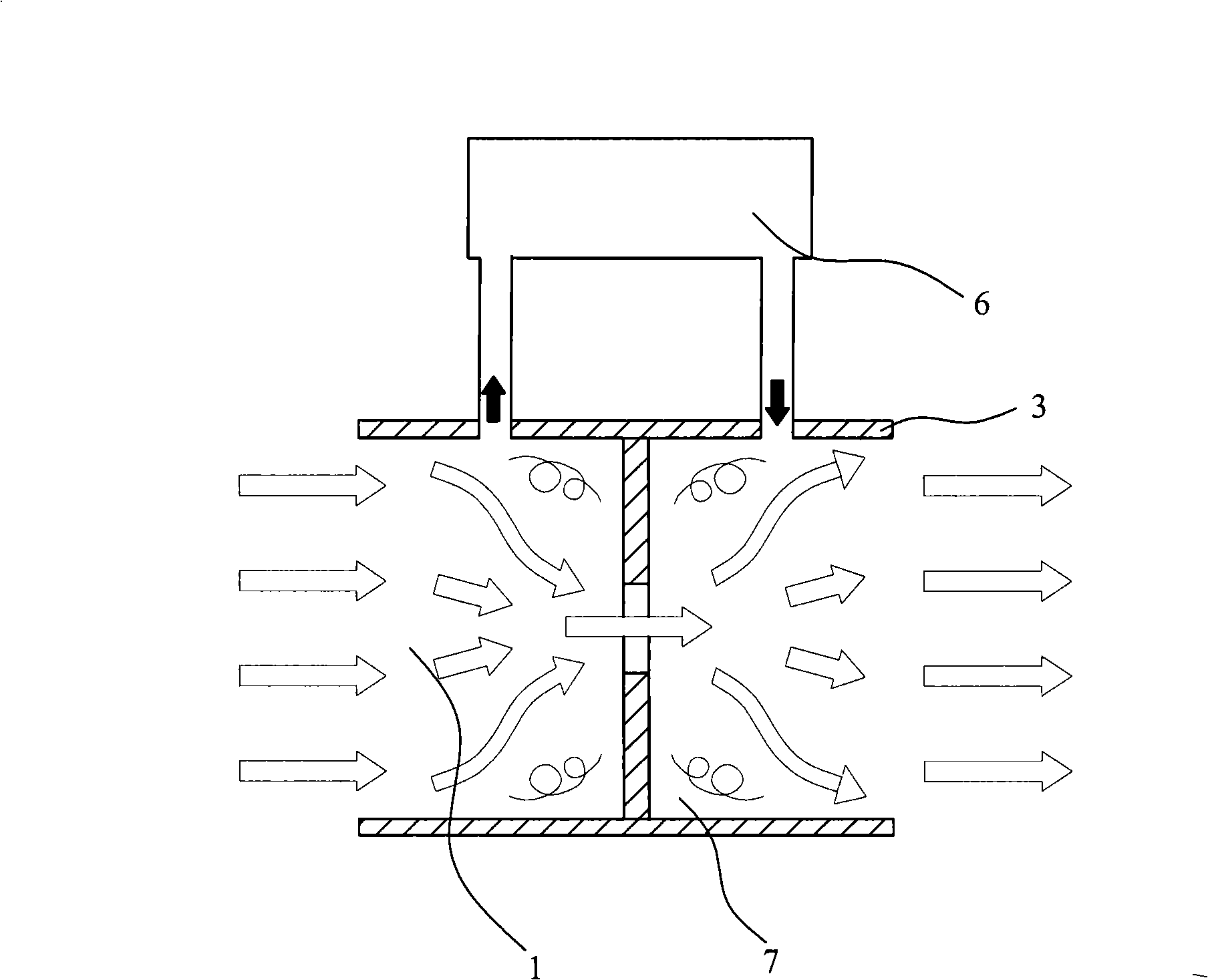
Its obvious disadvantages are: low measurement accuracy; narrow range; high installation conditions; large pressure loss; and turbulent flow easily occurs before and after the plate orifice of the plate orifice differential pressure flowmeter, which has a great impact on the measurement accuracy and does not meet medical requirements. High-precision measurement requirements in the field
In addition, the different geometric dimensions of the sampling channel and the size of the throttling device that creates the resistance of the main channel will also have a greater impact on the measurement performance

Method used


Image

  • Breathing machine and its low differential pressure type flow quantity detection mechanism
  • Breathing machine and its low differential pressure type flow quantity detection mechanism
  • Breathing machine and its low differential pressure type flow quantity detection mechanism

Examples


Embodiment Construction

[0016] Exemplary embodiments of the present invention will be described below with reference to the accompanying drawings. In the drawings, the same components are denoted by the same reference numerals.

[0017] The technical scheme adopted in the present invention:

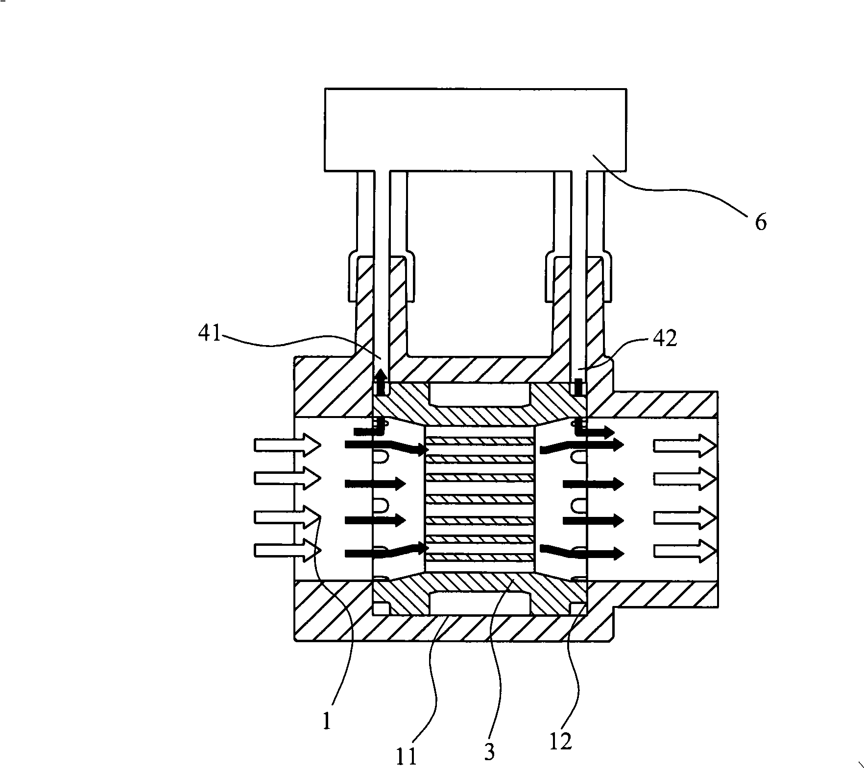
[0018] Such as figure 2 As shown, a specially designed independent throttling device 3 is placed in a section of the circular main gas path 1. The throttling device 3 is composed of several rings nested together. The main gas path 1 includes two sampling ports 41 and 42, the sampling port is respectively connected to the inlet and outlet of the metering device 6 that adopts a high-sensitivity mass flow sensor. The main air circuit 1 also includes a limiting end surface 12 , the throttling device 3 is installed in cooperation with the limiting end 12 , and the sampling ports 41 and 42 are just above the two ends of the throttling device 3 .

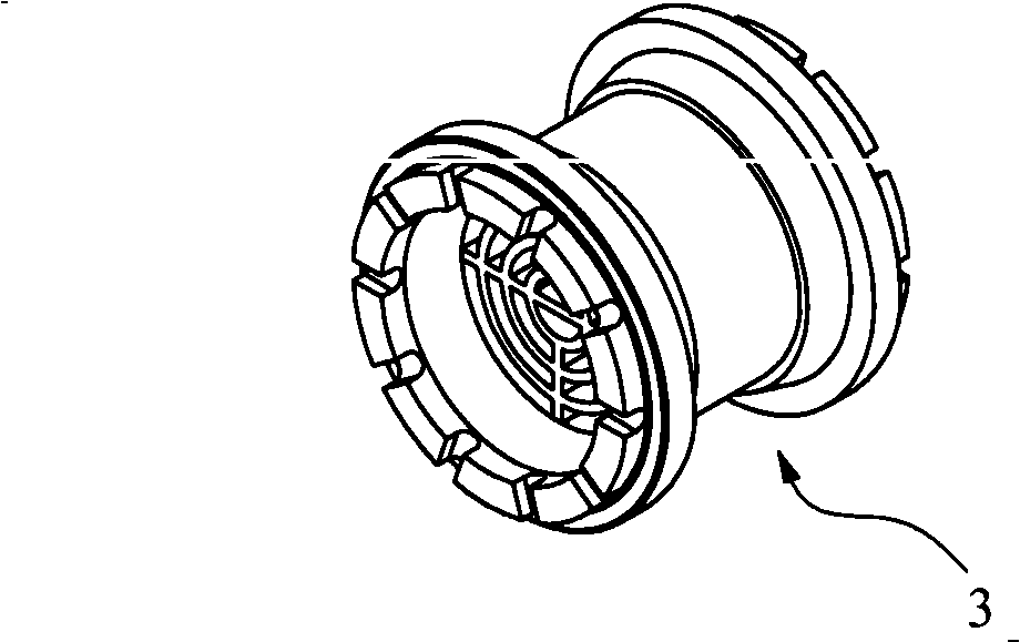
[0019] What Fig. 3 shows is described special throttling device 3, ...


PUM


Abstract

The invention relates to a low differential stress flow detection mechanism, comprising a main gas path (1), a throttling gear (3), a first sampling port (41), a second sampling port (42) and a metering device (6); wherein, the throttling gear (3) is arranged in the main gas path (1); the first sampling port (41) and the second sampling port (42) are positioned in the main gas path (1) and are respectively arranged at the front end and the back end of the throttling device (3); the gauging device (6) is connected with the first sampling port (41) and the second sampling port (42); the throttling gear (3) is provided with a plurality of concentric orifices (32) which are uniformly distributed around a central axis. The mechanism also relates to a ventilator which adopts the flow detection mechanism.

Description

technical field [0001] The invention relates to a low-differential-pressure flow detection mechanism, which is used in the field of medical ventilating equipment such as a ventilator or an anesthesia machine to perform high-precision flow measurement on low-pressure and low-flow gas. The invention also relates to a ventilator adopting the flow detection mechanism. Background technique [0002] During the use of medical devices such as ventilators and anesthesia machines, patients must be mechanically ventilated. For patients undergoing treatment, the control of ventilation volume is very important, especially for infants and critically ill patients. Inappropriate ventilation can bring danger to the patient. Therefore, the control of the ventilation flow is very important, which requires accurate measurement of the ventilation flow. [0003] There are many ways to measure gas, and the basic principle of the differential pressure bypass system used in the present invention i...

Claims


Application Information

Patent Timeline
Patent Type & Authority Applications(China)
IPC IPC(8): G01F1/40A61M16/00
Inventor 闫国平邓咏如孙小敏
Owner BEIJING AEONMED
Learn More