
Printing press cylinder

A technology for printing presses and cylinders, applied in printing presses, rotary printing presses, printing and other directions, can solve the problems of temperature rise, bending, adverse effects on printing quality, etc., to reduce the risk of bending, high stability, and reduce local Dangerous effects of temperature rise

Inactive Publication Date: 2008-11-26
M A N ROLAND DRUCKMASCHINEN AG
View PDF0 Cites 3 Cited by
  • Summary
  • Abstract
  • Description
  • Claims
  • Application Information

AI Technical Summary

Problems solved by technology

A printing press cylinder with such a large axial width tends to lead to bowing and to localized temperature rises
This may adversely affect print quality

Method used


Image

  • Printing press cylinder
  • Printing press cylinder

Examples


Embodiment Construction

[0010] The invention relates to a printing press cylinder of a printing press, in particular a rotary printing press.

[0011] The printing press cylinder according to the invention may be a plate cylinder, a transfer cylinder or also a planetary cylinder. Furthermore, the printing press cylinder according to the invention may also be an inking roller, a dampening roller or also a sheet feeding roller.

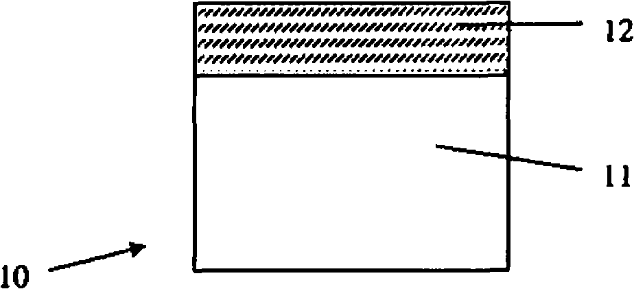
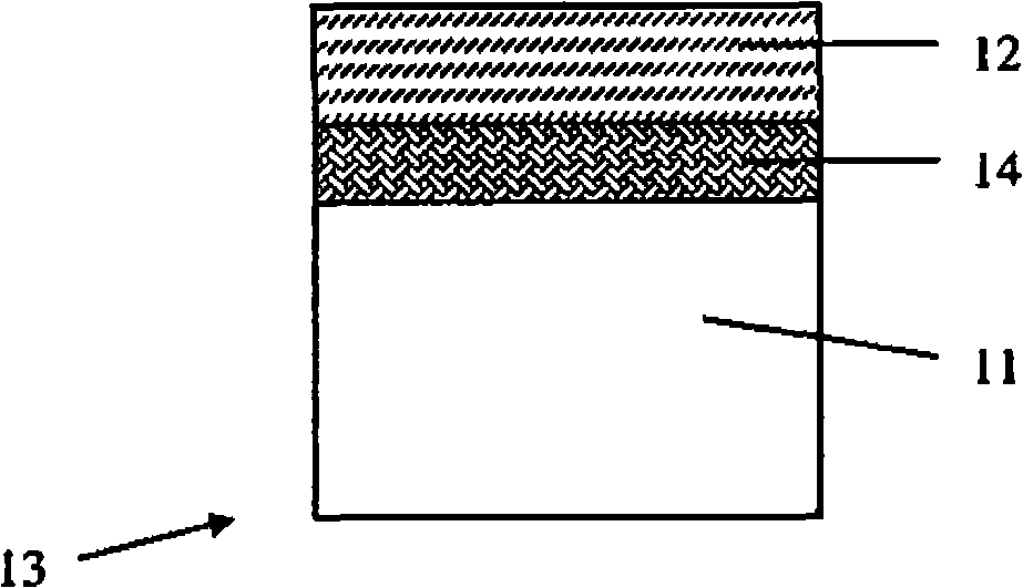
[0012] FIG. 1 shows a section through a part of a printing press cylinder 10 according to the invention, wherein the printing press cylinder 10 according to FIG. 1 has a cylinder base body 11 and a functional layer 12 applied to the cylinder base body. The functional layer 12 forms the outer surface of the printing press cylinder 10 .

[0013] In the sense of the invention, the drum base body 11 is formed from textile fibers impregnated with phenolic resin. Alternatively, the drum base 11 may also be formed of cardboard. A drum base body 11 formed of phenolic resin-impregna...


PUM


Abstract

The invention relates to a printing machine roller (10) with a roller basal body (11) and a function layer forming an outer surface of the printing machine. According to the invention, the roller basal body (11) is made of textile fabric or hardboard soaked by phenolic resin.

Description

technical field [0001] The invention relates to a printing press cylinder according to the preamble of claim 1 . Background technique [0002] In addition to a plate cylinder for receiving at least one printing plate, the printing unit of the printing press also has a transfer cylinder for accommodating the transfer die. The plate cylinder is also called the plate cylinder, and the transfer cylinder is also called the rubber cylinder. The impression cylinder and the transfer cylinder work together, wherein in a printing unit of a rotary printing press with several printing units, such an impression cylinder can be used either as a planetary cylinder or as a transfer cylinder of an adjacent printing unit. In addition to the plate cylinder, transfer cylinder and impression cylinder, other cylinders or rollers are installed in the printing press, such as inking rollers, dampening rollers and feed rollers in rotary printing presses. If the concept of a printing press cylinder ...

Claims


Application Information

Patent Timeline
Patent Type & Authority Applications(China)
IPC IPC(8): B41F13/08B41N7/00
CPCB41N7/04B41F13/08B41F31/26B65H2404/552B65H27/00B65H2401/112B65H2401/111B65H2801/21B41N7/06B41N7/00B41N2207/02B41N2207/14B41N2207/04B41N2207/10B41F31/00
Inventor T·博克R·克拉曼
Owner M A N ROLAND DRUCKMASCHINEN AG
Learn More