
AC plasma ejecting gun

A technology of launching gun and plasma, applied in the field of ion launching gun, can solve problems such as unmanned application of AC plasma, and achieve the effect of ensuring service life, improving service life and ensuring stability

Active Publication Date: 2012-12-12
北京光耀环境科技有限公司
View PDF0 Cites 0 Cited by
  • Summary
  • Abstract
  • Description
  • Claims
  • Application Information

AI Technical Summary

Problems solved by technology

[0005] The generation of AC plasma by AC direct power supply has not been applied at home and abroad.

Method used


Image

  • AC plasma ejecting gun
  • AC plasma ejecting gun
  • AC plasma ejecting gun

Examples


Embodiment approach 1

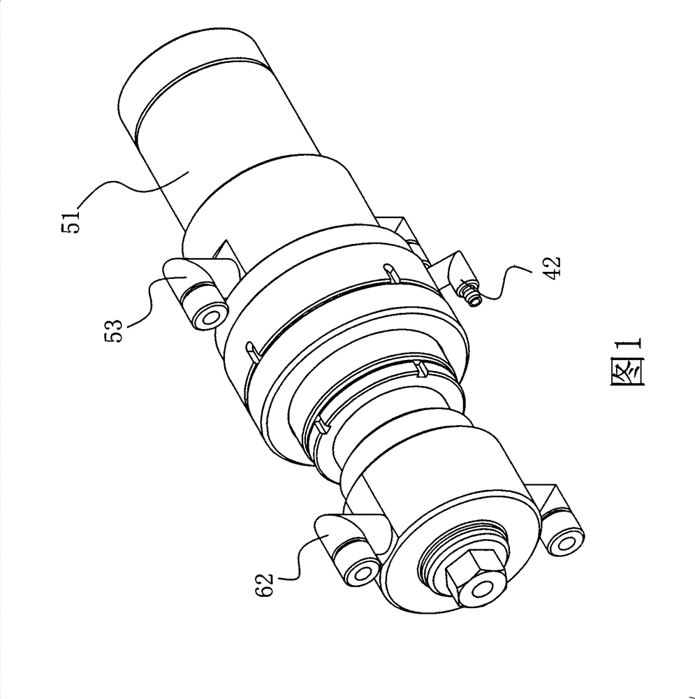
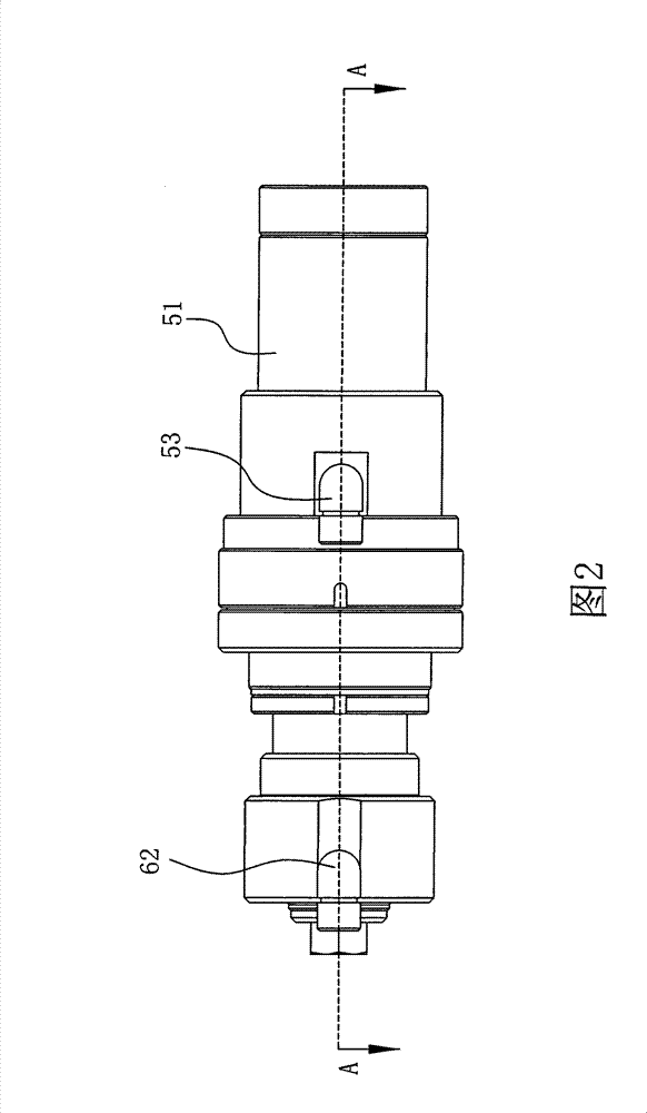
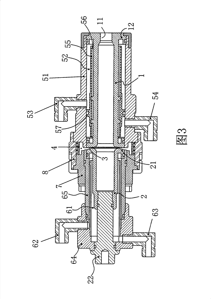
[0032] like Figure 1-4 As shown, the present invention proposes an AC plasma launch gun, which can directly utilize a single-phase power supply in 380V AC to generate plasma. The firing gun includes a front electrode 1 and a rear electrode 2 . The front electrode 1 can be a hollow cylindrical electrode, and is connected to the zero line of the power supply. The outlet end of the front electrode 1 (ie, the end far away from the rear electrode 2 ) is provided with a nozzle 11 . The rear electrode 2 can be a hollow cylindrical electrode, and is connected to the live wire of the power supply, and the end of the rear electrode 2 away from the front electrode 1 is closed. There is a gap 3 between the end surfaces of the front and rear electrodes, the gap is preferably 1-4mm, and a swirl air intake ring 4 is provided, the air inlet of the swirl air intake ring 4 is located outside the gap 3, Make the compressed air pass through the swirl inlet ring 4 to form a supersonic swirling ...

Embodiment approach 2

[0041] On the basis of the above-mentioned embodiment, the closed end of the rear electrode 2 is connected with a terminal 22, and the axial direction of the terminal 22 is provided with a through hole (not shown) for connecting compressed air, and the compressed air flows from the The through hole enters the inner wall of the rear electrode 2, and while cooling the rear electrode 2, it can also move the arc forward.

[0042] Other structures, working principles, and beneficial effects of this embodiment are the same as those of Embodiment 1, and will not be repeated here.


PUM


Abstract

The invention discloses an alternative current plasma emitting gun, which comprises a front electrode and a rear electrode, wherein the front electrode is connected with the null line of a power supply, a spraying nozzle is arranged at the outlet end of the front electrode, the rear electrode is connected with the firing line of the power supply, and one end of the rear electrode which is far away from the front electrode is sealed; a clearance is arranged between the front electrode and the rear electrode, and a swirl air inlet ring is also arranged between the front electrode and the rear electrode, and the air inlet opening of the swirl air inlet ring is positioned at the outer side of the clearance; and an insulating ring is connected with the front electrode and the rear electrode. In the alternative current plasma emitting gun, the plasma body can be generated through the alternative current, and the service life of the alternative current plasma emitting gun can be improved.

Description

technical field [0001] The invention relates to an AC plasma emission gun. Background technique [0002] Plasma generators can provide an efficient and clean heat source - plasma flow, which is widely used in power plant boiler ignition, cutting, welding, spraying, metallurgy, chemical and waste treatment and other industrial fields, as well as materials, aerospace science field. Thermal plasma has a high temperature and energy density, and contains a considerable number of charged particles (electrons and ions). It is different from high-temperature gases generated by chemical combustion. Many processes that could not be completed in the past can be achieved under plasma conditions. Well realized. In the past 20 years, arc plasma technology has developed rapidly and has a wide range of applications in the industrial field. [0003] After 2000, DC plasma ignition technology has been successfully applied to boilers in China. The so-called DC plasma ignition technology is ...

Claims


Application Information

Patent Timeline
Patent Type & Authority Patents(China)
IPC IPC(8): H05H1/32H05H1/34H05H1/28F23Q7/02
Inventor 陈光荣蒋迪杨雪赵虎军李滨
Owner 北京光耀环境科技有限公司
Learn More