
Refrigeration cycle apparatus

A refrigeration cycle and control device technology, used in refrigerators, refrigeration components, refrigeration and liquefaction, etc., can solve the problems of reduced exhaust gas refrigerant, poor exhaust bypass effect, long defrosting time, etc. Road resistance, small flow resistance, and effect of reducing influence

Inactive Publication Date: 2008-11-19
PANASONIC CORP
View PDF1 Cites 11 Cited by
  • Summary
  • Abstract
  • Description
  • Claims
  • Application Information

AI Technical Summary

Problems solved by technology

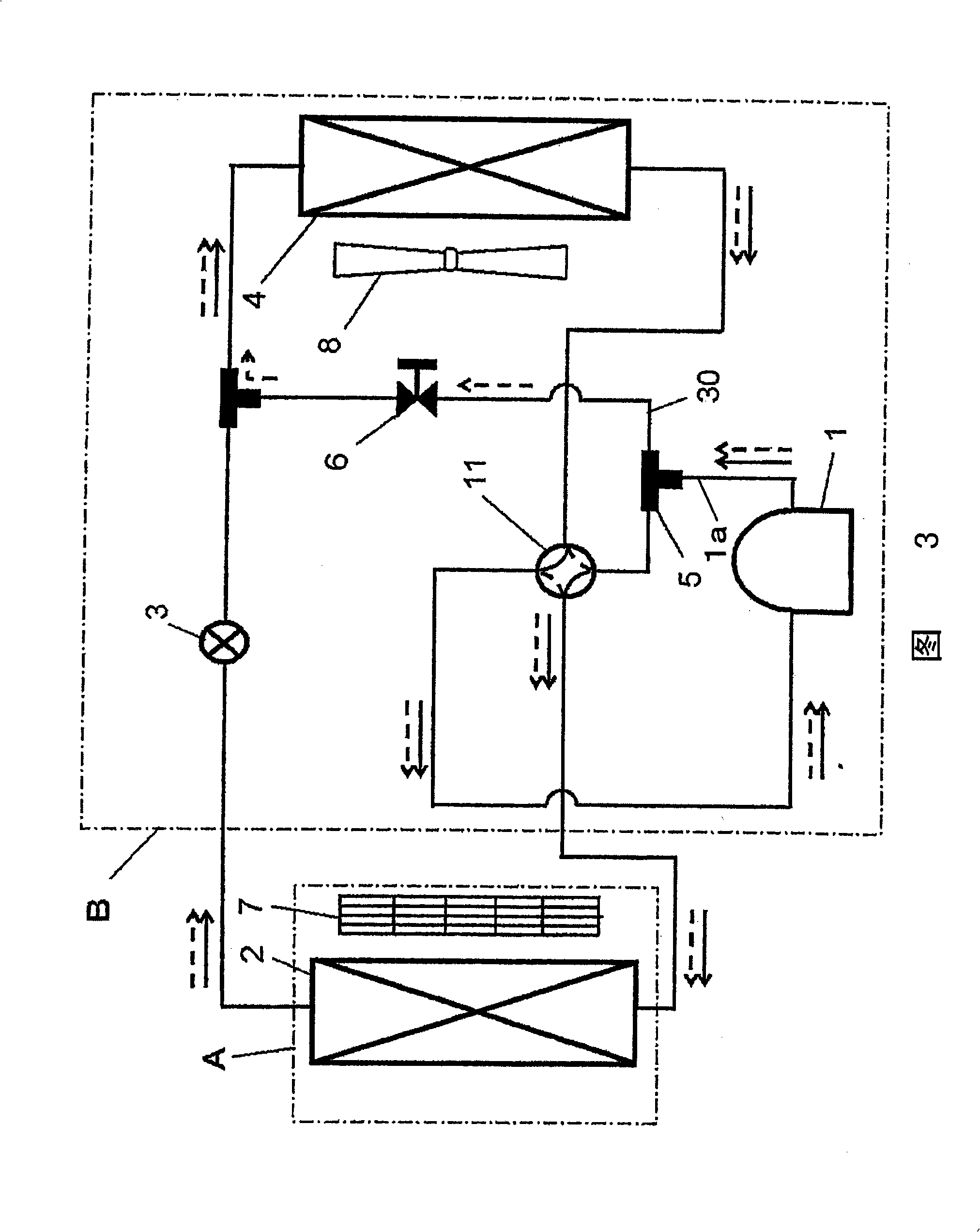
[0006] However, in the above-mentioned conventional structure, branch pipes are generally provided in the direction in which the main flow of the refrigerant discharged from the compressor flows toward the condenser, and basically a large amount of refrigerant flows to the condenser by using the exhaust bypass. When the discharge pressure is low, the amount of exhaust gas refrigerant that bypasses the condenser and flows into the evaporator is further reduced, so the effect of the exhaust bypass is poor, and the defrosting time is long. In addition, if you want to make as much exhaust gas as possible Refrigerant flows around the condenser, so the refrigerant control devices such as solenoid valves installed on the exhaust bypass must select devices with extremely small flow path resistance, so the cost increases

Method used


Image

  • Refrigeration cycle apparatus
  • Refrigeration cycle apparatus
  • Refrigeration cycle apparatus

Examples


Embodiment Construction

[0031] Hereinafter, referring to the drawings, an embodiment of the refrigeration cycle apparatus of the present invention will be described by taking the case of being installed in an air conditioner as an example. The present invention is not limited to this embodiment.

[0032] (Embodiment 1)

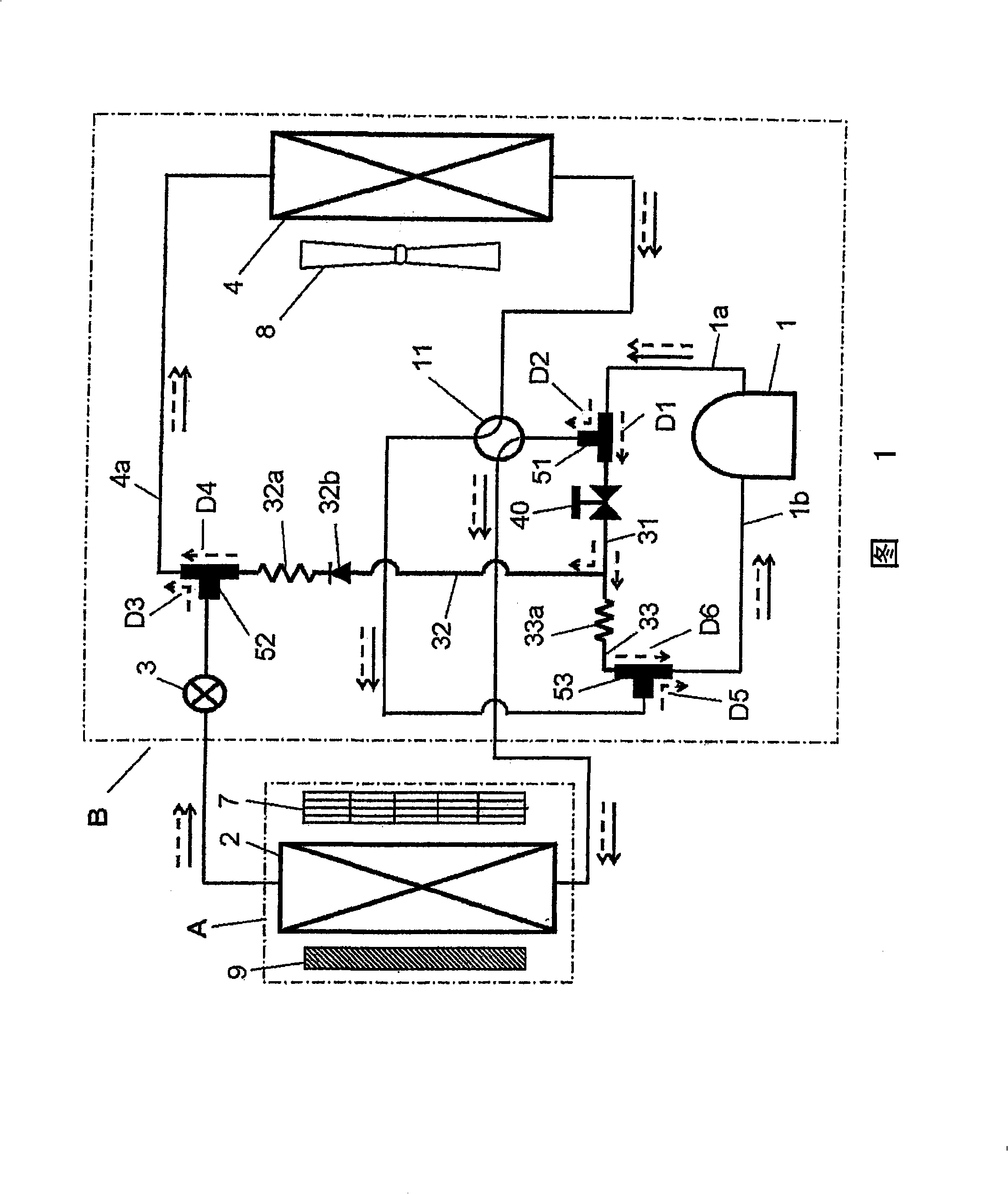
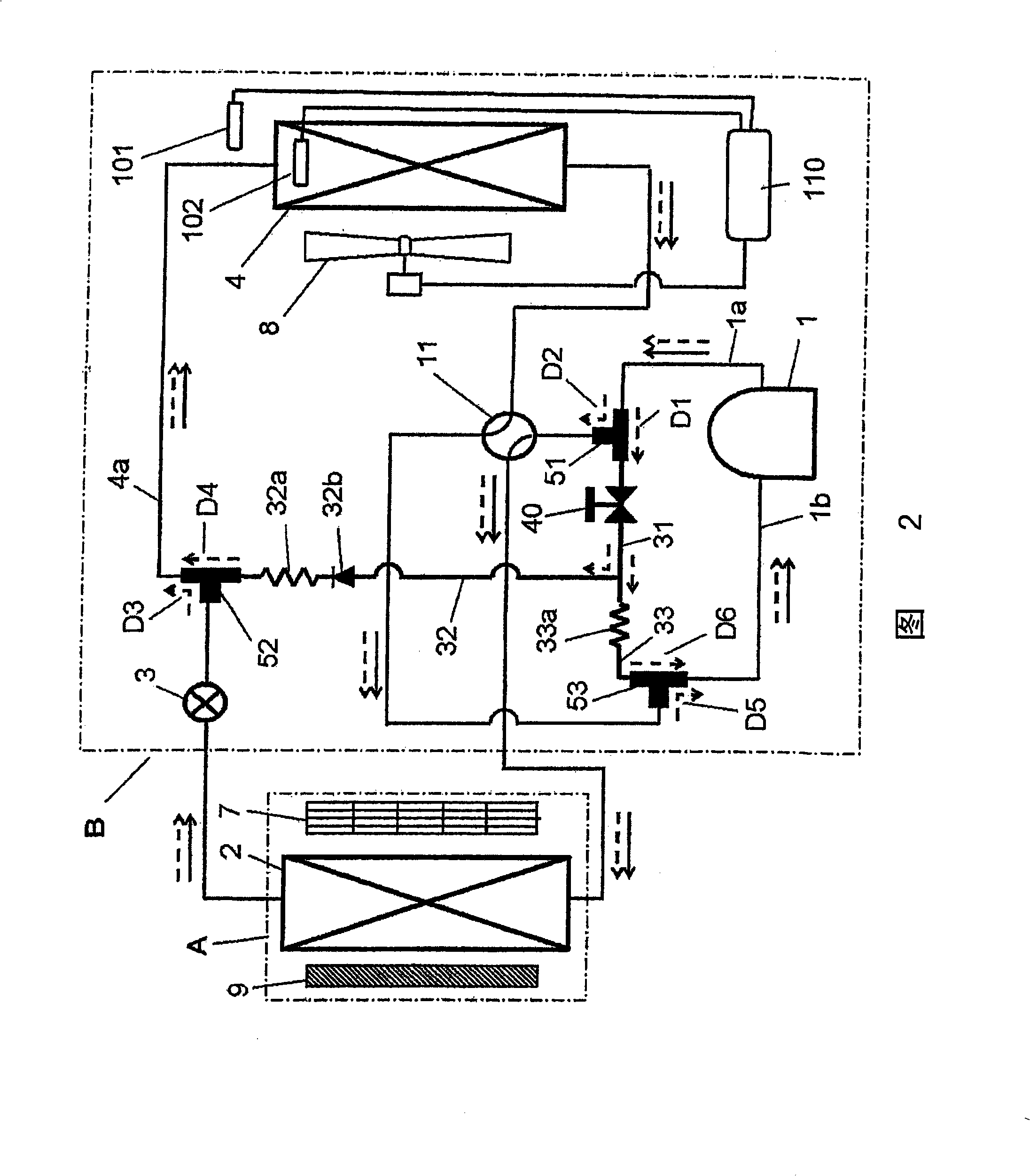
[0033] Fig. 1 is a refrigerant system diagram of a refrigeration cycle device according to Embodiment 1 of the present invention, showing the refrigerant flow of an air conditioner (in the direction of solid arrows during heating operation, and in the direction of dotted arrows in defrosting operation). In Fig. 1, compressor 1 for compressing refrigerant, four-way valve 11 for changing refrigerant flow, condenser 2 for condensing high-pressure and high-temperature refrigerant, throttling device 3 for decompressing condensed refrigerant, The evaporators 4 for evaporating the depressurized refrigerant are connected sequentially through piping to constitute a normal refrigeration cycle...


PUM


Abstract

A refrigeration cycle apparatus for effectively performing defrosting, in which a compressor (1), a four-way valve (11), a condenser (2), a throttling device (3), and an evaporator (4) are connected via pipes, including: discharge gas bypasses (31, 32, 33) for flowing a discharge refrigerant to at least one of a suction pipe (1b) of the compressor and an evaporator pipe (4a) for connecting the throttling device and the evaporator, from a discharge pipe (1a) for connecting the compressor and the four-way valve; and a refrigerant controller (40) capable of optionally flowing the discharge refrigerant to the discharge gas bypasses, wherein the discharge refrigerant of the compressor is partially passed through the discharge gas bypasses during defrosting in a heating operation, and a flow rate to the discharge gas bypasses is larger than a flow rate to the four-way valve.

Description

technical field [0001] The present invention relates to a refrigeration cycle device having a bypass circuit for melting frost adhering to an evaporator using exhaust gas refrigerant from a compressor. Background technique [0002] In conventional refrigeration cycle devices of this type, frost adheres to the evaporator depending on the operating conditions, resulting in a decrease in capacity. That is, the high-temperature and high-pressure exhaust gas refrigerant compressed in the compressor flows into the condenser through the four-way valve, and the refrigerant is condensed by heat exchange. The condensed refrigerant is decompressed by the throttling device, becomes a gas-liquid two-phase state, flows into the evaporator, evaporates through heat exchange, and is sucked into the compressor through the four-way valve again. Here, when the ambient temperature of the evaporator is low, frost gradually adheres to the evaporator, and the capacity decreases as the amount of fr...

Claims


Application Information

Patent Timeline
IPC IPC(8): F25B13/00F25B47/02
Inventor 高桥正敏田积欣公野间富之
Owner PANASONIC CORP
Learn More