
High effective concentration magnetic separator for concentrating strongly magnetic mineral

A strong magnetic and magnetic separator technology, applied in the direction of magnetic separation, solid separation, chemical instruments and methods, etc., can solve the problems of increasing the difficulty of concentration and filtration operations, difficulty in solid-liquid separation of final products, poor concentration effect, etc., to achieve dehydration The effect is remarkable, the speed is continuously adjustable, and the effect is flexible

Inactive Publication Date: 2010-06-02
WUHAN UNIV OF TECH
View PDF5 Cites 0 Cited by
  • Summary
  • Abstract
  • Description
  • Claims
  • Application Information

AI Technical Summary

Problems solved by technology

It causes difficulty in solid-liquid separation of the final product and increases the difficulty of concentration and filtration operations.
The concentrated magnetic separator currently used in production has poor concentration effect, low concentration and small processing capacity

Method used


Image

  • High effective concentration magnetic separator for concentrating strongly magnetic mineral
  • High effective concentration magnetic separator for concentrating strongly magnetic mineral
  • High effective concentration magnetic separator for concentrating strongly magnetic mineral

Examples


Embodiment Construction

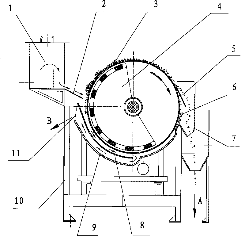
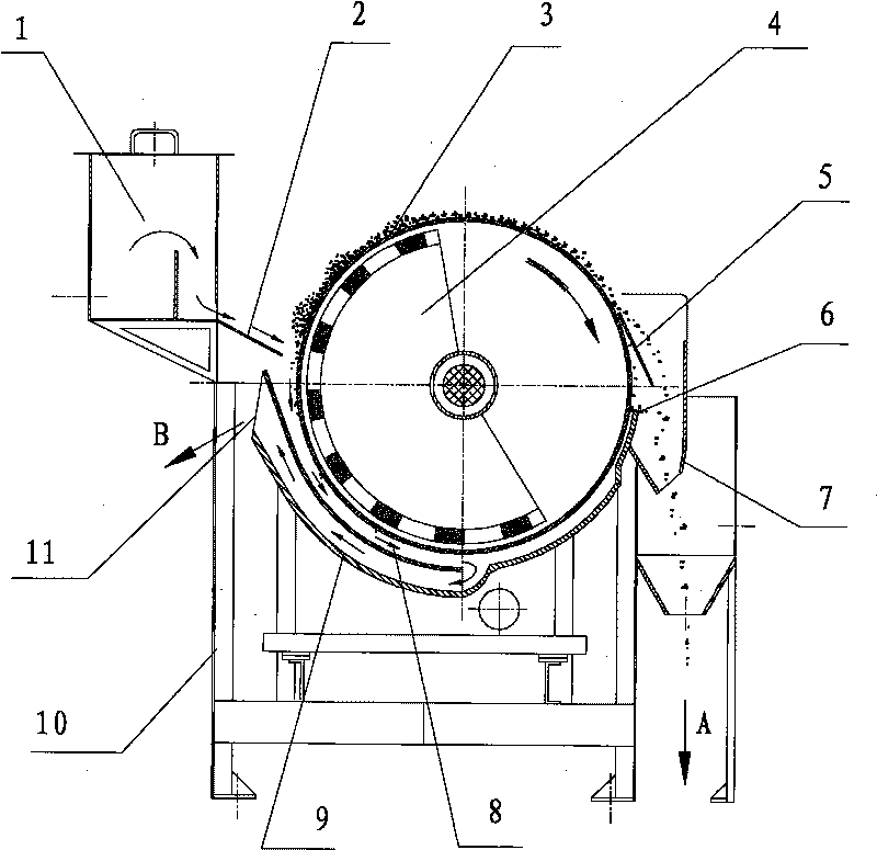
[0018] Such as figure 1 As shown, the high-efficiency concentration magnetic separator for the concentration of strong magnetic minerals includes a feeding box 1, a deflector 2, a cylinder 3, a permanent magnet 4, an unloading plate 5, a damping plate 6, and a collecting bucket 7. Sorting plate, bottom box 9, frame 10; Cylinder 3 is a cavity, and permanent magnet 4 is arranged in the cavity of cylinder 3, and permanent magnet 4 is fixedly connected with cylinder 3, and the shaft on cylinder 3 The two ends are respectively connected by bearings with the frame 10 (that is, the cylinder can rotate under the action of the transmission mechanism), and the shaft on the cylinder 3 is connected with the transmission mechanism; The upper end surface is an arc-shaped surface, and the bottom box 9 is fixedly connected with the frame 10 (such as welding or bolting); a sorting plate is arranged between the cylinder 3 and the bottom box 9, and the sorting plate is located at the left part o...


PUM


Abstract

The invention relates to a device used for the condensation of strong magnetic mineral. An efficient condensation magnet separator used for the condensation of strong magnetic mineral is characterizedin that the efficient condensation magnet separator comprises a feeding box, a guide plate, a circular cylinder, a permanent magnet, an unloading plate, a damper, a collecting bucket, a separation plate, a bottom box and a frame; the permanent magnet is arranged in the cavity of the circular cylinder, and an axle on the circular cylinder is connected with a transmission mechanism; the bottom boxis arranged at the lower part of the circular cylinder, the separation plate is arranged between the circular cylinder and the bottom box, a separation groove is formed between the separation plate and the circular cylinder, and a overflow channel is formed between the separation plate and the bottom box; the feeding box is positioned on the left side of the circular cylinder, the guide plate is fixedly connected in the opening position of the feeding box, and the guide plate is positioned at the upper part of the separation groove; the collecting bucket is positioned on the right side of thecircular cylinder, and the collecting bucket is fixedly connected with the frame; the unloading plate is positioned in the collecting bucket, the unloading plate and the circular cylinder are distributed in the tangential direction, and the unloading plate is fixedly connected with the frame. The condensation magnet separator has the advantages that the content of the product solids after the condensation is high, and the condensation effect is good.

Description

technical field [0001] The invention relates to a device for concentrating strong magnetic minerals. Background technique [0002] Chinese mineral processing experts proposed to use the technology of "improving iron and reducing impurities" to "reduce silicon (impurity) before iron", forming the theory of "maximizing the group's interests" in iron and steel enterprises, and promoting the rapid development of mineral processing technology and the iron and steel industry. 90% of the iron minerals in my country's iron concentrates are magnetite. The iron concentrates after iron extraction and impurity reduction must be concentrated and dehydrated first, and then filtered to obtain the final iron concentrates as iron-making raw materials. [0003] In mineral processing production, different types and performances of concentration pools (machines) (or thickeners) are generally used for the concentration of concentrated ore after separation; for the concentration of strong magneti...

Claims


Application Information

Patent Timeline
Patent Type & Authority Patents(China)
IPC IPC(8): B03C1/10
Inventor 罗立群方勇
Owner WUHAN UNIV OF TECH
Learn More