Switching power supply circuit and surge absorbing circuit

A switching power supply and switching circuit technology, applied in the direction of high-efficiency power electronic conversion, electrical components, output power conversion devices, etc., can solve the problems of power supply efficiency limitation and large number of components, and achieve the effect of suppressing surge and improving power supply efficiency

Active Publication Date: 2008-11-12
SHINDENGEN ELECTRIC MFG CO LTD
View PDF1 Cites 7 Cited by
  • Summary
  • Abstract
  • Description
  • Claims
  • Application Information

AI Technical Summary

Problems solved by technology

[0010] However, according to the lossless snubber circuit in the above-mentioned prior art, the number of parts is large, and many elements are interposed in the current path until the surge is released to the output terminal. limited in efficiency

Method used


Image

  • Switching power supply circuit and surge absorbing circuit
  • Switching power supply circuit and surge absorbing circuit
  • Switching power supply circuit and surge absorbing circuit

Examples


Embodiment Construction

[0037] Hereinafter, embodiments of the present invention will be described with reference to the drawings.

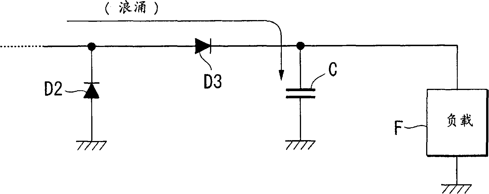
[0038] First, refer to figure 1 The principle of the surge absorbing circuit in the switching power supply device according to the embodiment of the present invention will be described.

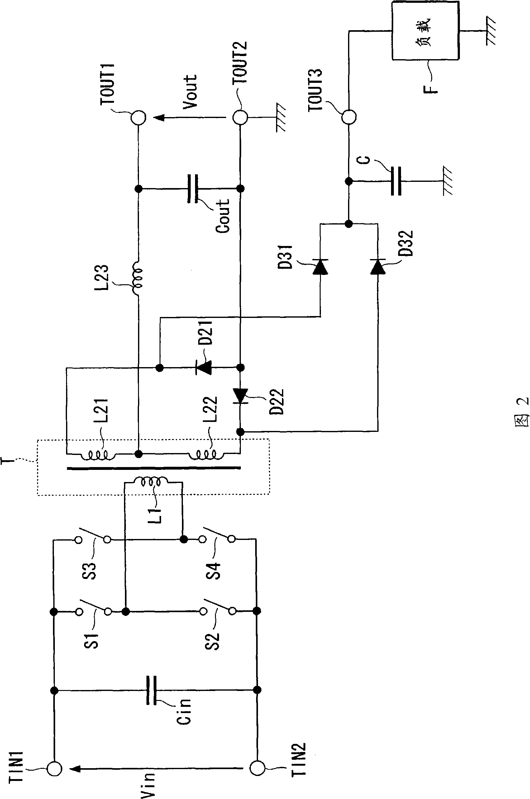
[0039] exist figure 1 Among them, the diode D2 corresponds to the main diodes D21 and D22 provided on the secondary side shown in FIG. 2 above. The diode D3 and the capacitor C constitute the surge absorbing circuit of the present invention. The predetermined load F is any device that operates the capacitor C as an auxiliary power supply, and its content is not particularly limited.

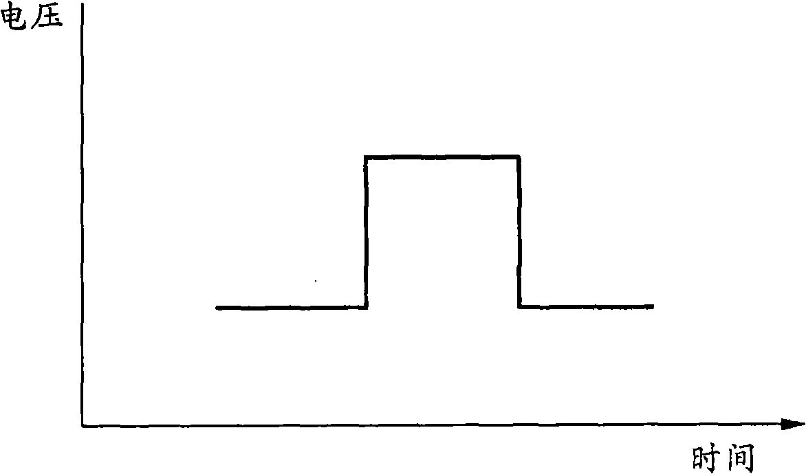
[0040] exist figure 1 , the cathode side of diode D2 generates as above Figure 5 When the surge is shown, the surge is supplied to the capacitor C through the diode D3, and the capacitor C is charged. In other words, the surged power is stored in the capacitor C. The electric power stored in the...


PUM


Abstract

Provided is a switching power supply device capable of effectively improving power supply efficiency with a small number of parts. The switching power supply device includes: a switching circuits (S1 to S4) for converting DC input power into AC power, a transformer (T) having a primary winding to which the AC power is supplied, first rectifiers (D21, D22) for rectifying the AC power induced by the secondary winding of the transformer into DC power, second rectifiers (D31, D32) having anodes connected to cathodes of the first rectifiers, and a capacitor (C) connected between the cathodes of second rectifiers and a predetermined potential node and functioning as an auxiliary power source of a predetermined load (F). Surge generated at the cathodes of the first rectifiers (D21, D22) of the secondary side during switching is supplied to the capacitor (C) via the second rectifiers (D31, D32). The load (F) uses power charged in the capacitor as an operation power source.

Description

technical field [0001] The present invention relates to a switching power supply device and a surge absorbing circuit, and particularly relates to a technique for suppressing a surge generated in a rectifier provided on the secondary side of a transformer in the switching power supply device. [0002] this application claims priority based on Japanese Patent Application No. 2005-375148 for which it applied to Japan on December 27, 2005, and uses the content here. Background technique [0003] FIG. 4 shows the structure of a conventional switching power supply device. The switching power supply device shown in FIG. 4 includes an input capacitor Cin, switches S1-S4, a transformer T, diodes D21, D22, an output winding L23, and an output capacitor Cout. [0004] According to this switching power supply device, once the DC input power of a predetermined voltage (Vin) applied between the input terminal TIN1 and the input terminal TIN2 is converted into AC power by the switching o...

Claims


Application Information

Patent Timeline
Patent Type & Authority Applications(China)
IPC IPC(8): H02M7/21H02M3/28
CPCH02M1/14H02M7/062H02M3/285H02M3/33523H02M3/33592Y02B70/10H02M1/12H02M3/28
Inventor 多田信裕
Owner SHINDENGEN ELECTRIC MFG CO LTD
Why Eureka
Try Eureka