DC giant wheel hydroturbine

A Ferris wheel and water turbine technology, applied in water wheel, tidal flow/damless hydropower, mechanical equipment, etc., can solve problems such as low power generation head, not reaching the stage of large-scale commercial development, and deep excavation of machine pits. The effect of cost reduction in kilowatts

Inactive Publication Date: 2008-11-12
林斌炎
View PDF0 Cites 5 Cited by
  • Summary
  • Abstract
  • Description
  • Claims
  • Application Information

AI Technical Summary

Problems solved by technology

After the 20th century, with the continuous increase of energy consumption and the emergence of the oil crisis, the utilization and development of new energy and energy conservation and emission reduction have been valued by countries all over the world. Among them, tidal energy is the focus of each country's competing development. This inexhaustible Although the natural and clean energy has huge reserves, it has not yet reached the stage of large-scale commercial development. The main reasons are: the power generation head is low, and equipment protection in seawater is difficult.
The use of conventional low-head axial-flow or tubular turbines requires high manufacturing and materials, and a large amount of civil engineering. Conventional turbines have submerged draft pipes, and the excavation of machine pits is very deep, which makes the installed cost per kilowatt high, resulting in tidal currents. Poor economical ability to develop and utilize

Method used


Image

  • DC giant wheel hydroturbine
  • DC giant wheel hydroturbine

Examples


Embodiment Construction

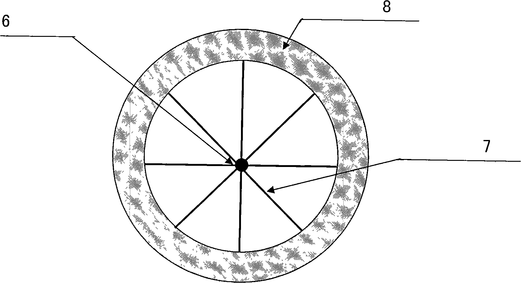
[0013] The present invention will be described in detail below in conjunction with accompanying drawing: figure 1 , 2 As shown, the present invention mainly consists of a water turbine (1), a speed increaser (2) and a generator (3) to form a generating set, and the water turbine (1) axle (4) is supported on the water turbine support. The water turbine of the present invention is mainly composed of a wheel shaft (6), a steel wheel frame (7) and a semi-closed wheel blade (8). The speed increaser (2) of the present invention is an intermeshing gear speed increase mechanism or a belt pulley transmission speed increase mechanism; the speed increaser (2) is two types of drive wheel transmission configuration or drive shaft transmission configuration. The structure of the speed increaser is a conventional technology, so like the generator described in the present invention, it belongs to the conventional technology mastered by those skilled in the art.

[0014] The ferris wheel wat...


PUM


Abstract

The invention discloses a uniflow type ferris-wheel hydraulic turbine connected with a generator by a speed increaser. A ferris-wheel-shaped mechanism consists of an axle, steel wheel carrier and built-in vanes; the uniflow ferris-wheel hydraulic turbine is positioned in a flow channel of a special-purpose wheel groove; the axle is fixed on hydraulic turbine supports arranged at the two sides of the flow channel; the uniflow ferris-wheel hydraulic turbine adopts lever principle; a runner with large diameter is huge like a ferris wheel; a circle of the vanes are arranged at the perimeter of the runner; therefore, the uniflow ferris-wheel hydraulic turbine is obtained; the uniflow ferris-wheel hydraulic turbine makes use of the pressure flow of potential energy difference between up stream and down stream to push directly the vanes on the ferris-wheel to lead the hydraulic turbine to rotate and is characterized by simple structure, low requirements for materials, convenient manufacture, easy maintenance and low cost; as the hydraulic turbine is not required to be buried deeply in water, the quantity of civil engineering including flow channel is reduced by times; the horizontal set ensures that the hydraulic turbine operates with stand-alone configuration or a plurality of hydraulic turbines carry out parallel operation, when in parallel operation, the hydraulic turbines can lead the unit capacity of the generator to be increased by times. By adopting a low-head hydroelectric generating set provided with the novel uniflow ferris-wheel hydraulic turbine, the comprehensive cost of per kilowatt installation is reduced by times, compared with the conventional generating set.

Description

technical field [0001] The invention relates to a novel low water head and large flow tidal energy hydroelectric power generation device, which belongs to a kind of hydroelectric power generation equipment. technical background [0002] Power generation technology has long been a mature application technology. It is equipped with different power generation equipment according to different power generation methods. For example, thermal power generation must be equipped with gas turbines, and hydropower generation must be equipped with different types of water turbines according to the height of the power generation head. The above various mature power generation technologies can all find corresponding disclosed technologies one by one in Chinese patent bulletins and textbooks. After the 20th century, with the continuous increase of energy consumption and the emergence of the oil crisis, the utilization and development of new energy and energy conservation and emission reducti...

Claims


Application Information

Patent Timeline
Patent Type & Authority Applications(China)
IPC IPC(8): F03B7/00F03B13/26
CPCY02E10/223Y02E10/28Y02E10/20Y02E10/30Y02P70/50
Inventor 林斌炎
Owner 林斌炎
Why Eureka
Try Eureka