
Method for switching message of switching network, switching device, route line card and Ether line card

A technology of message switching and switching devices, applied in the field of switching networks

Active Publication Date: 2008-11-05
北京紫光通信科技集团有限公司
View PDF0 Cites 20 Cited by
  • Summary
  • Abstract
  • Description
  • Claims
  • Application Information

AI Technical Summary

Problems solved by technology

Therefore, this method of directly connecting to the Ethernet line card without any processing has not really realized that a switching device has two switching planes at the same time: the routing switching plane and the Ethernet switching plane

Method used


Image

  • Method for switching message of switching network, switching device, route line card and Ether line card
  • Method for switching message of switching network, switching device, route line card and Ether line card
  • Method for switching message of switching network, switching device, route line card and Ether line card

Examples


Embodiment 1

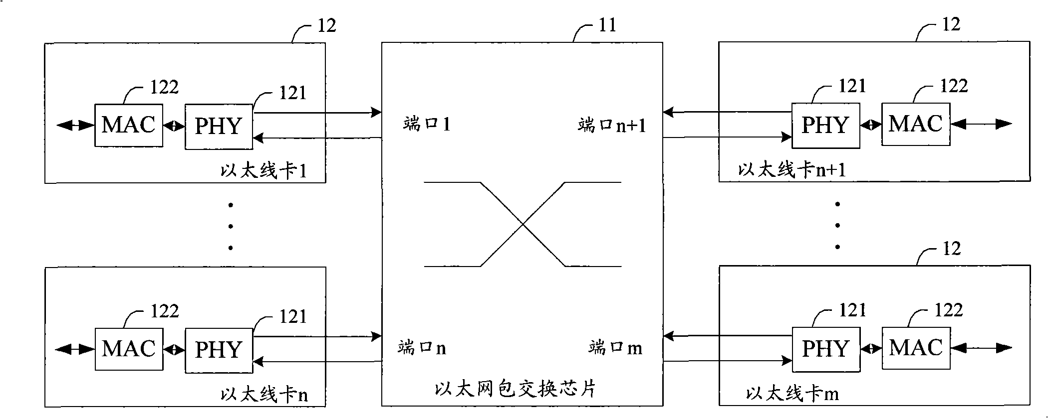
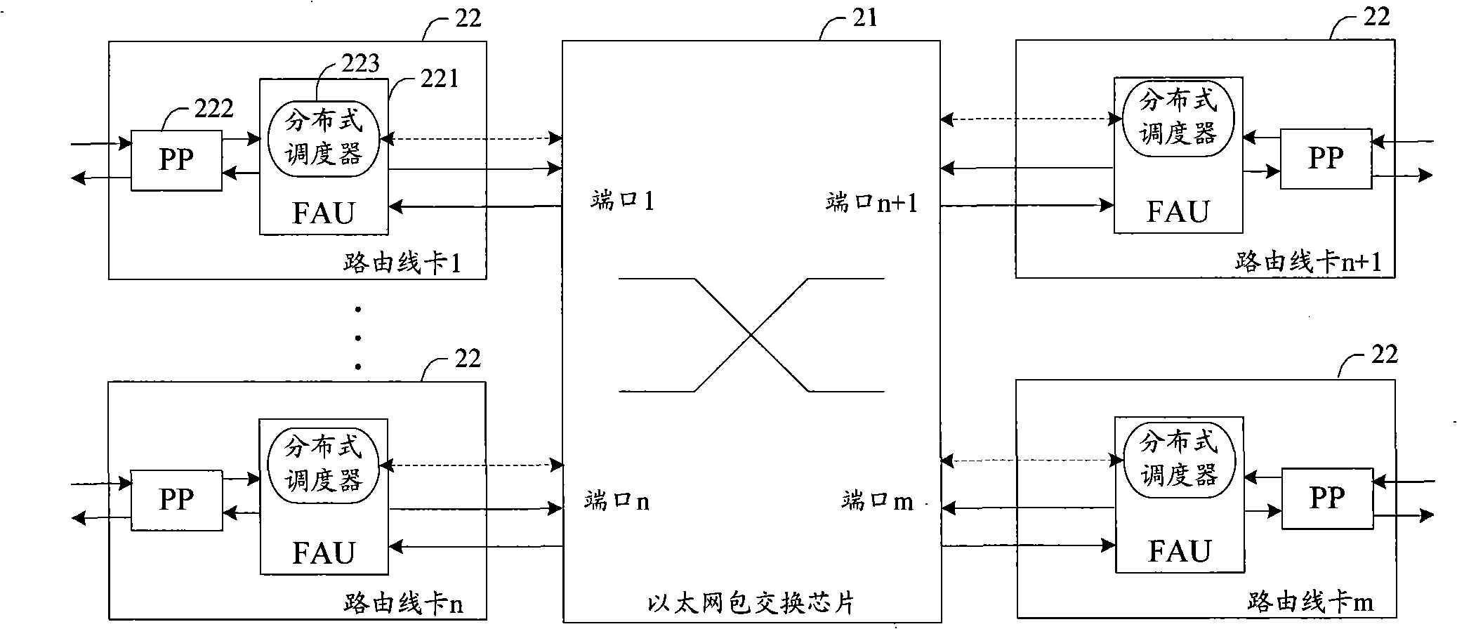
[0053] In this embodiment, the process of sending a message from a routing line card to a routing line card and sending a message from a routing line card to an Ethernet line card shown in FIG. 4 is described. LC0 and LC1 in Figure 4 are routing line cards, and LC2 is an Ethernet line card.

[0054] First, before switching, the internal cache in the packet switching chip is allocated according to the following rules.

[0055] 1) Cache allocation in the output direction:

[0056] a1. Allocate the output buffer in the total buffer of the packet switching chip to each output port, and the allocation principle can be equal allocation. Each outgoing port uses its own buffer. For ease of understanding, the port that receives messages from the line card is called an inbound port, and the port that outputs messages to a line card is called an outbound port. Those skilled in the art can understand that a port can be an outbound port and an inbound port at the same time. .

[0057] ...

Embodiment 2

[0121] In this embodiment, the process of sending a message from the Ethernet line card to the routing line card and sending a message from the Ethernet line card to the Ethernet line card shown in FIG. 7 is described. Same as the first embodiment, the destination line card in this embodiment is still the routing line card LC1 and the Ethernet line card LC2, the difference is that the source line card in this embodiment is the Ethernet line card LC3.

[0122] Firstly, before the switching, the on-chip buffer in the packet switching chip and the receiving buffer queue of the routing line card LC1 are allocated. The distribution method is the same as the corresponding distribution method in the first embodiment. The receive buffer of Ethernet line card LC2 and the send buffer of LC3 are not divided into queues.

[0123] Figure 8 It shows the processing flowchart of LC3 sending a message to the packet switching chip in the second embodiment of the present invention. Such as ...


PUM


Abstract

The invention discloses a method for switching message of switching network, a switching device, a route line card and an ether line card. The method includes: allocating independent output buffer for each port of the switching device; dividing the output buffer of each port into mutually independent output buffer queue corresponding to various line cards, according to the types of the line card capable of being inserted; the switching device, switching a message that the line card types of the source line card and the object line card are same, to the output buffer queue corresponding to the object line card type at the port for inserting the object line card. Application of the invention can realize at least two switching planes at one switching device.

Description

technical field [0001] The invention relates to switching network technology, in particular to a message switching method applied to a switching network, a switching device, a routing line card and an Ethernet line card. Background technique [0002] In order to expand port density, currently switching devices such as routers and switches usually adopt a modular system structure. The modular system structure includes a switching fabric backplane and multiple line cards plugged into the switching fabric backplane. Multiple line cards exchange packets through the switching network provided by the switching network backplane. It can be seen that the switching network is the core part for completing packet exchange between line cards. [0003] The switching network of a modular Ethernet switch is called an Ethernet switching plane. The Ethernet switching plane is a switching plane that prioritizes switching efficiency and allows packet loss to avoid congestion and affect subs...

Claims


Application Information

Patent Timeline
Patent Type & Authority Applications(China)
IPC IPC(8): H04L12/56H04L12/02H04L12/861
Inventor 余昌刚
Owner 北京紫光通信科技集团有限公司
Learn More