Pyromagnetic release

A technology of thermal magnetic release and tripping, which is applied in the direction of protection switch operation/release mechanism, etc. It can solve the problems of unreliable action, complex structure, cumbersome tripping process, etc., and achieve the effect of reliable action and simple tripping process

Active Publication Date: 2008-11-05
CHANGSHU SWITCHGEAR MFG CO LTD (FORMER CHANGSHU SWITCHGEAR PLANT)
View PDF0 Cites 13 Cited by
  • Summary
  • Abstract
  • Description
  • Claims
  • Application Information

AI Technical Summary

Problems solved by technology

Therefore, this structure is more complicated, and the process of jumping buttons is cumbersome.
Moreover, in the thermal-magnetic release structure with thermal-magnetic fault indication (display) of the circuit breaker, the drawbar of the circuit breaker is divided into two shaft-connected thermal adjustment drawbars and magnetic trip drawbars, which are used for thermal overload protection respectively. And short-circuit and overload play a protective role. If the above-mentioned push rod structure is used again, after the subsequent functional module (which can provide a tripping signal such as a leakage functional module) of the circuit breaker detects the working current, the functional module release will strike The push rod installed in the upper cover of the circuit breaker, and then the push rod strikes the draw rod of the thermal magnetic tripper, but no matter whether the thermal adjustment draw rod or the magnetic trip draw rod is hit, a false indication will be generated, and the action is unreliable, so that the above-mentioned The situation that the push rod of the thermal magnetic release of the structure directly hits the drawbar is no longer applicable

Method used


Image

  • Pyromagnetic release
  • Pyromagnetic release
  • Pyromagnetic release

Examples


Embodiment 1

[0023] Embodiment 1: The push rod 6 is installed between the bracket 2 and the base 1 .

[0024] The thermal-magnetic release of this embodiment is suitable for thermal-magnetic adjustable and non-adjustable thermal-magnetic circuit breakers, and is also suitable for circuit breakers with fault indication.

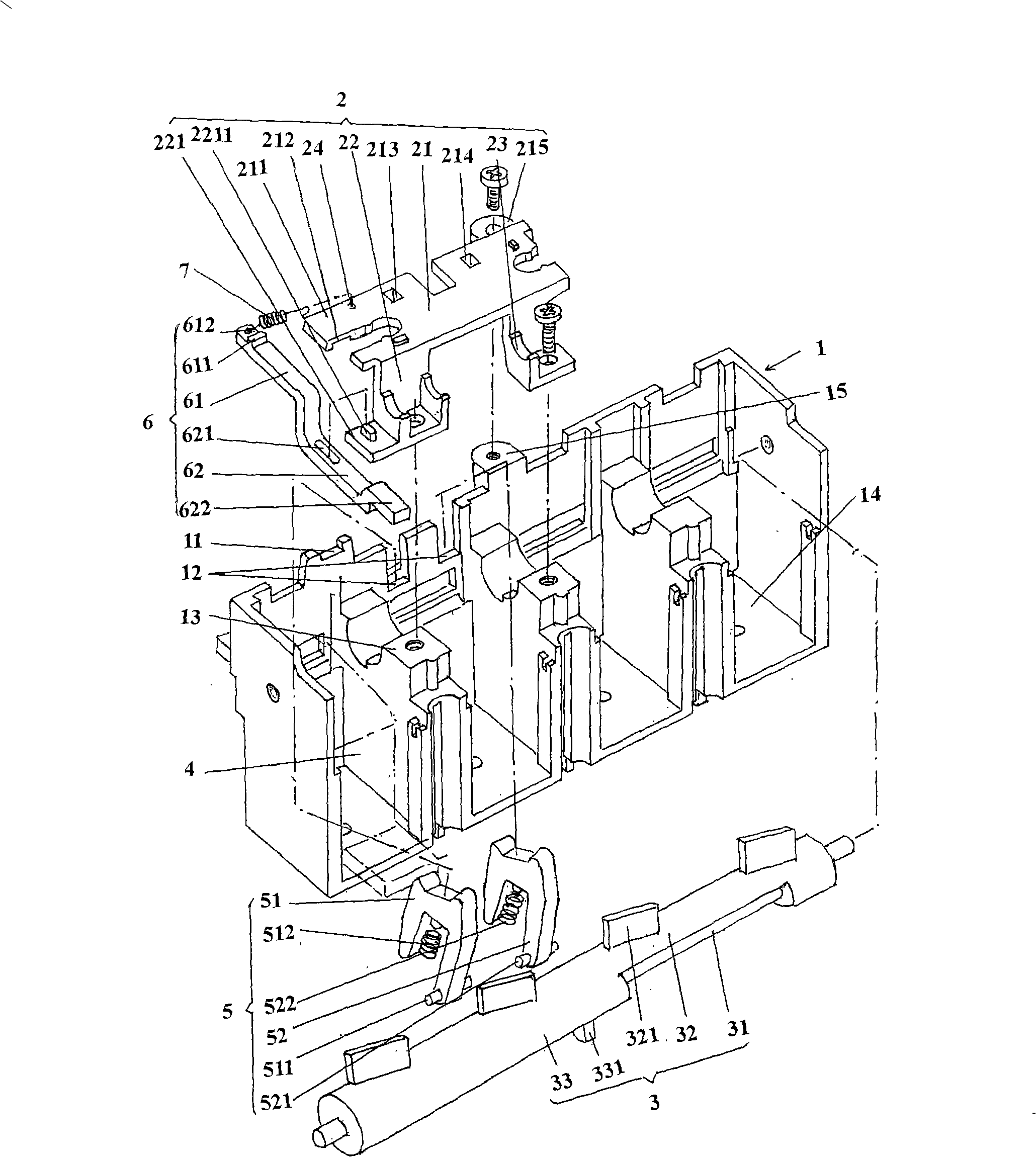
[0025] please see figure 1 and figure 2 , gives the base 1 on which four thermal-magnetic protection devices 4 can be installed, specifically: on one side of the base 1 in the length direction, that is, the current figure 1 The front side of the shown position state is divided into four thermal-magnetic protection device accommodation cavities 14, and four thermal-magnetic protection devices 4 are arranged in the four thermal-magnetic protection device accommodation cavities 14, thereby forming a four-pole circuit breaker , based on this principle, if three thermal-magnetic protection devices 4 are used, then it will appear as a three-pole circuit breaker, so this embod...

Embodiment 2

[0030] Embodiment 2: The push rod 6 is installed on the base 1 .

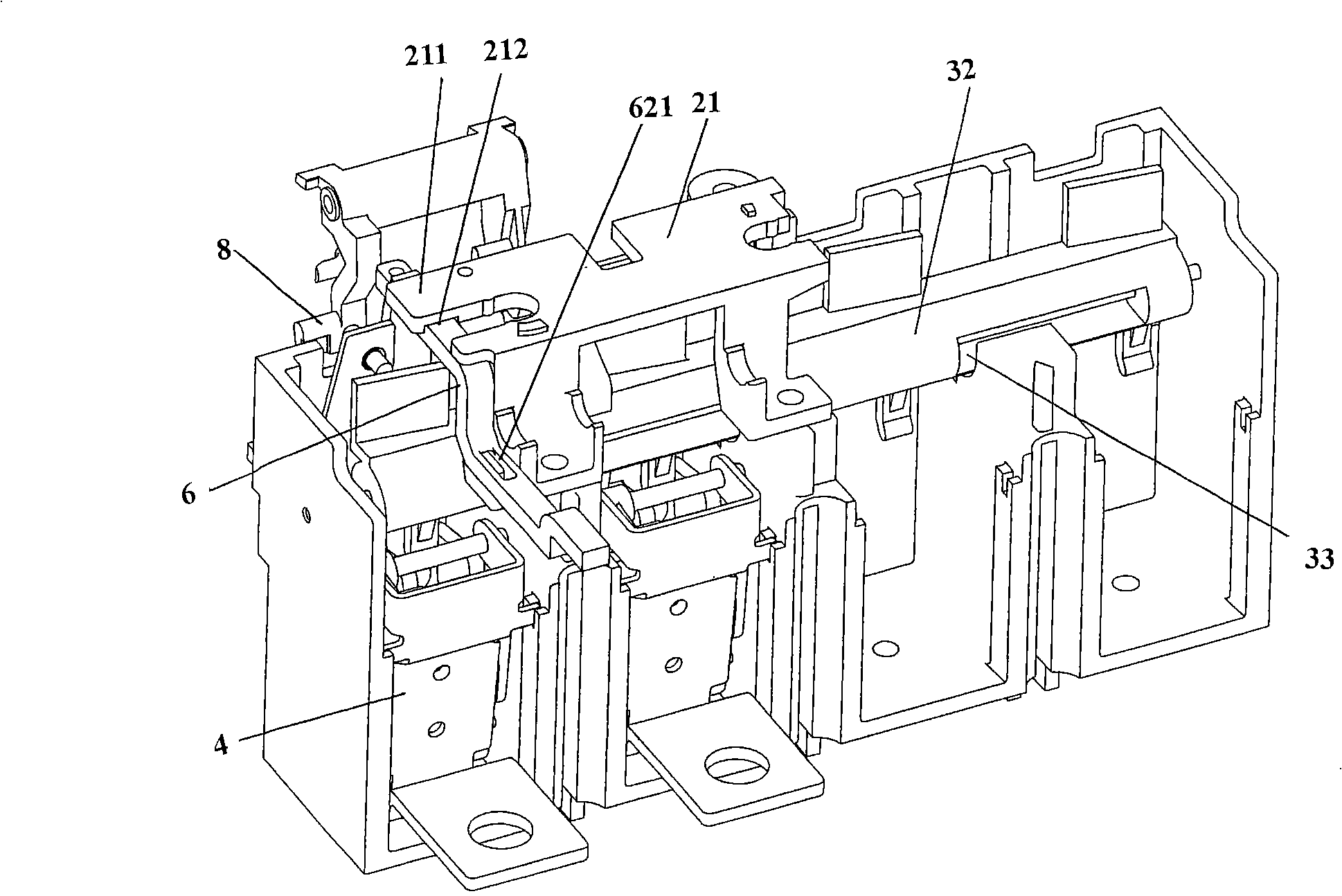
[0031] please see Figure 4 and Figure 6 , the present embodiment is applicable both with the support 2 and without the support 2, the barrier 13 for separating the thermomagnetic protection device 4 on the base 1 is extended with a section of boss 131, on the boss 131 A guide protrusion 1311 is added, and the guide hole 621 of the push rod 6 matches with the guide protrusion 1311 .

[0032] Whether the circuit breaker is equipped with a bracket or without a bracket 2, the upper limit of the push rod 6 can be limited by a stop protrusion 91 provided in the upper cover 9 of the circuit breaker, and the upper cover 9 and the base 1 are closed Finally, the stop protrusion 91 and the guide slide groove 11 on the base 1 are combined into a guide slide groove hole, thereby the push rod 6 can be limited, and when the push rod 6 is reset, the stop protrusion 611 and The blocking protrusion 91 in the loam cake 9 con...

Embodiment 3

[0034] Embodiment 3: The push rod 6 is installed on the bracket 2 .

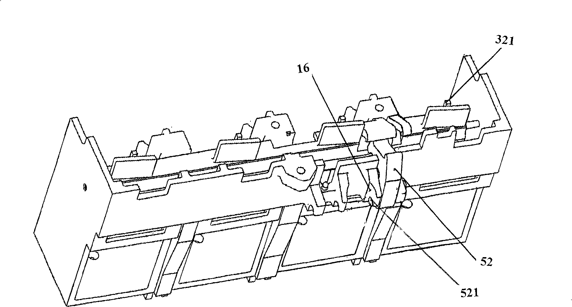
[0035] please see Figure 5 and Figure 7 , the support 2 of the present embodiment is based on the structure of the support 2 of the first embodiment and then a guide slide hole 216 is opened at the corresponding position of the notch blocking protrusion 211, so that the push rod 6 is installed in the guide slide hole 216 of the support 2, and the push rod 6 is additionally provided with a boss 623 for the limit of push rod 6 reset, when push rod 6 resets, moves to boss 623 and the side wall 92 contact of loam cake 9 ( Figure 7 Shown), that is, stop the movement, so that the push rod 6 will not fall off from the guide slide hole 216.

[0036] The thermal-magnetic release of this embodiment is suitable for thermal-magnetic adjustable and thermal-magnetic non-adjustable circuit breakers, and can also be used for circuit breakers with fault indication.

[0037] Please combine Figure 1 to Figure 5 , the t...


PUM


Abstract

A thermomagnetic releaser is arranged on the plastic case breaker, for directly striking the plastic case breaker operation mechanism locking device, which includes a base, a draw rod arranged on the base and a group of thermomagnetic protective device mounted on the base, characterized by also including a pushing rod slideably mounted on the base for causing the breaker operation locking device to act relative to the breaker operation locking device. The invention has the advantages of simple buckling process with no middle transistion tache, and no mistake indication is provided in the breaker thermomagnetic releaser with the thermomagnetic fault indication mechanism to ensure the action reliable.

Description

technical field [0001] The invention relates to a thermal magnetic tripper, which is arranged on a molded case circuit breaker and is used for directly hitting the tripper of the locking device of the operating mechanism of the molded case circuit breaker. Background technique [0002] Molded case circuit breakers are suitable for distribution networks with AC 50Hz, insulation voltage of 800V, and rated operating current of 690A and below. They are used to distribute electric energy and protect lines, power supplies and electrical equipment. The circuit breaker has overload, short circuit and undervoltage protection functions to avoid damage to lines and power supply equipment. [0003] The protection functions of molded case circuit breakers mainly include thermal overload protection, short circuit protection, time delay protection, electronic protection and leakage protection, etc. When implementing protection, circuit breakers, as traditional mechanical structures, gener...

Claims


Application Information

Patent Timeline
Patent Type & Authority Applications(China)
IPC IPC(8): H01H71/40
Inventor 唐维春吴海霞陈志刚王炯华管瑞良
Owner CHANGSHU SWITCHGEAR MFG CO LTD (FORMER CHANGSHU SWITCHGEAR PLANT)
Why Eureka
Try Eureka