Rotary device of medicine image-forming system
A technology for a medical imaging system and a rotating device, applied in the field of rotating devices, can solve the problems of ball damage, increased contact fatigue damage on the surface of the ball, high noise and vibration, and achieve the effects of ensuring stability and increasing the rotation speed.
- Summary
- Abstract
- Description
- Claims
- Application Information
AI Technical Summary
Problems solved by technology
Method used
Image


Examples
Embodiment 1
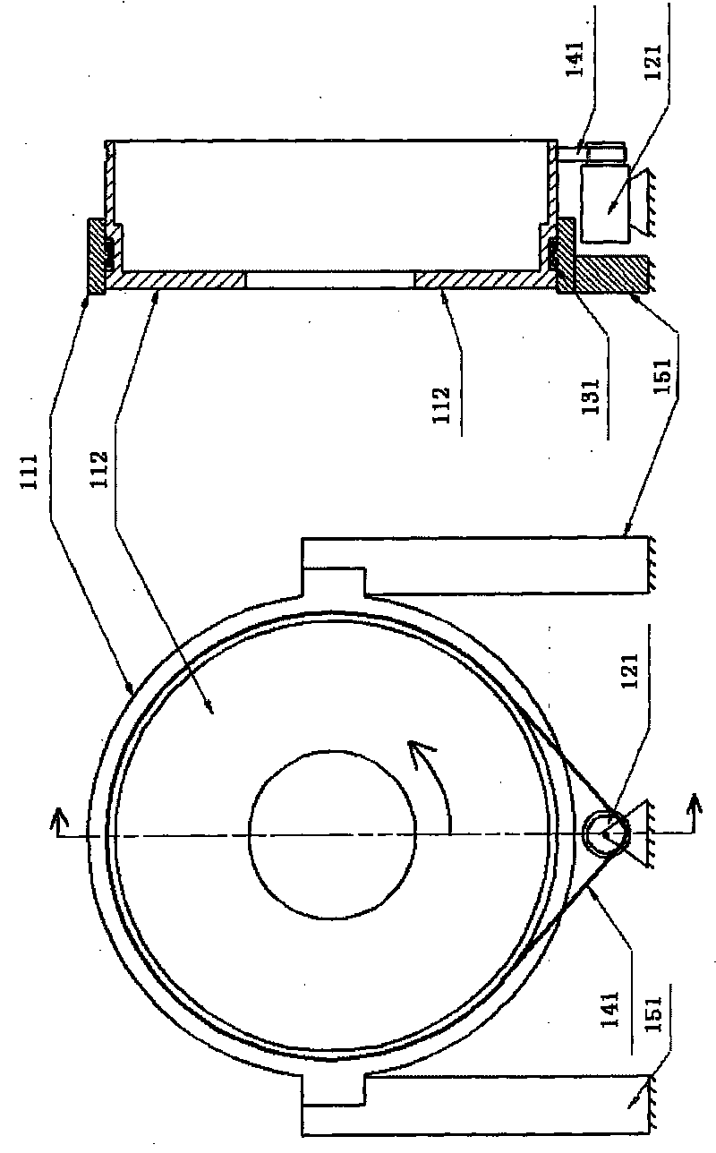
[0034] figure 2 It is a front view and a sectional view of a rotating device using double slewing bearings according to Embodiment 1 of the present invention, wherein the left figure is a front view, and the right figure is a sectional view along the A-A' axis of the left figure. Such as figure 2 As shown, the rotating device is installed on the fixed support 251 of the CT, and includes two nested slewing bearings, and the two nested slewing bearings are composed of a fixed outer ring 211 , a low-speed turntable 212 and a high-speed turntable 213 . Wherein, the fixed outer ring 211, the low-speed turntable 212 and the high-speed turntable 213 are three iron rings respectively.
[0035] The outer side of the fixed outer ring 211 is fixed on the support 251 of the CT frame, and the low-speed bearing driving device can be a low-speed bearing driving motor (or motor) 221, which is installed on the ground. The base of the CT frame can be placed on the ground, and the supports a...
Embodiment 2
[0047] image 3 It is a schematic cross-sectional view of a rotating device using double slewing bearings according to Embodiment 2 of the present invention. This cross-sectional view is also along the figure 2 The A-A' axis profile of the front view, with figure 2 The difference in the cross-section in is that, image 3 Only the section with the double slew bearing is shown, not the entire section.
[0048] This embodiment is basically the same as Embodiment 1, and also adopts a double bearing structure, and image 3 neutralize figure 2 The reference numerals with the same last two digits indicate components with the same function, and their functions will not be repeated here. Such as image 3 As shown, the difference between this embodiment and the first embodiment is that the low-speed bearing driving motor 321 is installed on the fixed outer ring 311 . In addition, in image 3 In , the X-ray tube 361 and the slip ring 371 installed on the high-speed turntable 31...
Embodiment 3
[0051] Figure 4 It is a front view and a sectional view of a rotating device using double slewing bearings according to Embodiment 3 of the present invention, wherein the left figure is a front view, and the right figure is a sectional view along the A-A' axis of the left figure.
[0052] This embodiment is basically the same as Embodiment 1, and Figure 4 neutralize figure 2 The reference numerals with the same last two digits indicate components with the same function, and their functions will not be repeated here. Such as Figure 4 As shown, the difference between this embodiment and Embodiment 1 is that the width of the low-speed turntable 412 is larger, at least larger than the width of the high-speed turntable 413, and its cross-sectional shape is concave, and the concave shape includes an upper side, a lower side and a vertical side. The low-speed turntable 412 surrounds the high-speed turntable 413 inside its notch, the high-speed bearing drive motor 422 is instal...
PUM
 Abstract
Description
Claims
Application Information
 - R&D
- Intellectual Property
- Life Sciences
- Materials
- Tech Scout
- Unparalleled Data Quality
- Higher Quality Content
- 60% Fewer Hallucinations
Browse by: Latest US Patents, China's latest patents, Technical Efficacy Thesaurus, Application Domain, Technology Topic, Popular Technical Reports.
© 2025 PatSnap. All rights reserved.Legal|Privacy policy|Modern Slavery Act Transparency Statement|Sitemap|About US| Contact US: help@patsnap.com