Control device of work machine
A technology for control devices and working machines, applied in hoisting devices, mechanical equipment, fluid pressure actuating devices, etc., can solve energy loss, deterioration of fuel consumption rate, deterioration of rotation and boom speed matching, and inability to apply boom and other problems, to achieve the effect of good speed matching and rotation speed suppression
Inactive Publication Date: 2008-10-29
KOMATSU LTD
View PDF2 Cites 23 Cited by
- Summary
- Abstract
- Description
- Claims
- Application Information
AI Technical Summary
Problems solved by technology
For this reason, the operator cannot fully operate the two operating levers 41, 42 in order to match the speed of the boom and the upper rotating body, and must carefully adjust
This requires the operator to be skilled and at the same time leads to deterioration of the operability of the lifting and rotating operation
2) Deterioration of energy loss and fuel consumption rate
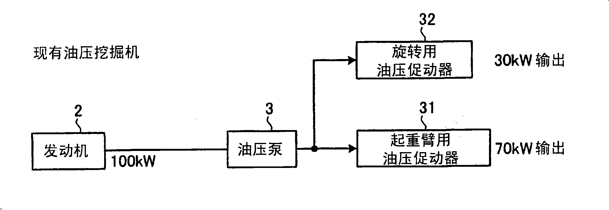
Therefore, 40kW is distributed to the generator motor 11 for rotation, and 80kW is distributed to the hydraulic actuator 31 for the boom, which deviates from the ideal state of power distribution (FIG. 2-1) as in FIG. 2-2. Faster than boom raising speed, resulting in poor match between rotation and boom speed
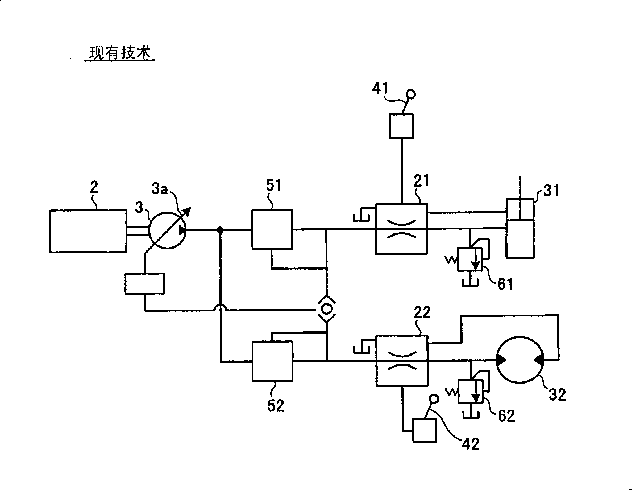
In addition, the structure shown in FIG. 3 cannot be applied to the boom, rotation, etc., because one actuator for the boom is the hydraulic actuator 31, and the other actuator for the rotation is the electric actuator 11. Existing technology based on the premise that both sides of the actuator are hydraulic actuators
In addition, the techniques described in Patent Documents 1 and 2, which are based on the premise that both the boom and the rotating actuator are hydraulic actuators, cannot be applied.
Method used
View moreImage
Smart ImageViewing Examples
Examples
Embodiment Construction
Login to View More PUM
 Abstract
A control device of a work machine capable of matching the speeds of both a hydraulic actuator and an electric actuator with each other when these actuators are operated in combination with each other. When a hydraulic cylinder (31) for a boom and a power generation motor (11) for turning are determined to be operated in combination with each other by determination parts (71, 72) based on the operating amounts of an operating lever (41) for the boom and an operating lever (42) for turning, the torque of the power generation motor (11) is limited based on a pump discharge pressure Pp and accordingly, for example, a torque limit instruction, for reducing the torque limit value TL2 of the power generation motor (11) as the discharge pressure Pp of a hydraulic pump (3) is reduced, is generated and output. A pump suction power instruction for limiting the suction power Wp of the hydraulic pump (3) is generated to reduce the suction power Wp of the hydraulic pump (3) as a turning output power Wsw is increased. An engine / pump controller (17) controls the hydraulic pump (3) so that the pump suction power of the hydraulic pump (3) does not exceed a calculated pump suction power Wp.
Description
Work machine controls technical field The present invention relates to a control device for a working machine, and in particular to a control device suitable for a hybrid construction machine which utilizes a generator-motor to assist engine driving force. Background technique One of the typical tasks performed by hydraulic excavators is lifting and rotating tasks. Lifting and rotating operation is to load the sand below with the boom, then rotate the upper rotating body at a predetermined angle (for example, 90°) while raising the boom, and load it on the loading platform of the dump truck. During lifting and turning work, the boom operating lever and the turning operating lever are combinedly operated, and the boom is raised and the upper revolving body is rotated at the same time. The configuration of a conventional construction machine 1 will be briefly described with reference to FIG. 1 . In addition, in FIG. 1, for convenience of explanation, only the structure fo...
Claims
Login to View More Application Information
Patent Timeline
 Patent Type & Authority Applications(China)
IPC IPC(8): E02F9/20E02F9/22F15B11/16F15B21/14
CPCE02F9/2037B66C1/42B66F7/04E02F9/2075
Inventor 森永淳河口正井上宏昭
Owner KOMATSU LTD
- R&D Engineer
- R&D Manager
- IP Professional
- Industry Leading Data Capabilities
- Powerful AI technology
- Patent DNA Extraction
Learn More Browse by: Latest US Patents, China's latest patents, Technical Efficacy Thesaurus, Application Domain, Technology Topic, Popular Technical Reports.
© 2024 PatSnap. All rights reserved.Legal|Privacy policy|Modern Slavery Act Transparency Statement|Sitemap|About US| Contact US: help@patsnap.com


