
Polarization spectroscopic device and projection display device using the same

A technology of polarization splitting and devices, which is applied in polarizing components, projection devices, optical components, etc., can solve problems such as insufficiency, and achieve good splitting and practical effects

Inactive Publication Date: 2008-10-29
JINGYING OPTICS
View PDF4 Cites 13 Cited by
  • Summary
  • Abstract
  • Description
  • Claims
  • Application Information

AI Technical Summary

Problems solved by technology

But this improvement is not enough, the extinction ratio of the reflective end is still less than 100:1

Method used


Image

  • Polarization spectroscopic device and projection display device using the same
  • Polarization spectroscopic device and projection display device using the same
  • Polarization spectroscopic device and projection display device using the same

Examples


Embodiment Construction

[0015] Specific embodiments of the present invention will be described below with reference to the accompanying drawings.

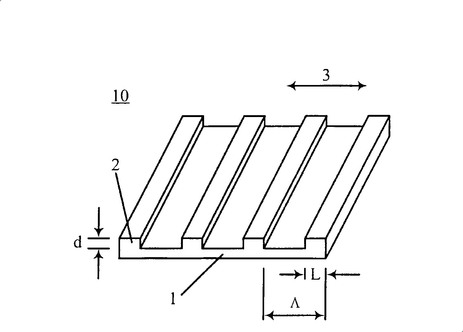
[0016] figure 1 A schematic structural diagram of an all-dielectric subwavelength grating is illustrated. Make a periodic dielectric wire grid relief pattern 2 on a piece of base material 1. The material of the wire grid 2 can be the same material as the base material 1, or a different material can be grown on the base material by thin film growth technology. 1, and then etched into a wire grid. When the period Λ of the wire grid is much smaller than the wavelength of the incident light, this structure is called a sub-wavelength grating 10 . Depending on the usage, the incident light can be visible light or infrared light, etc. Let the refractive index of the dielectric grating material be n G , and the duty ratio is f=L / Λ, then it can be approximated by the sub-wavelength:

[0017] n TE = ...


PUM


Abstract

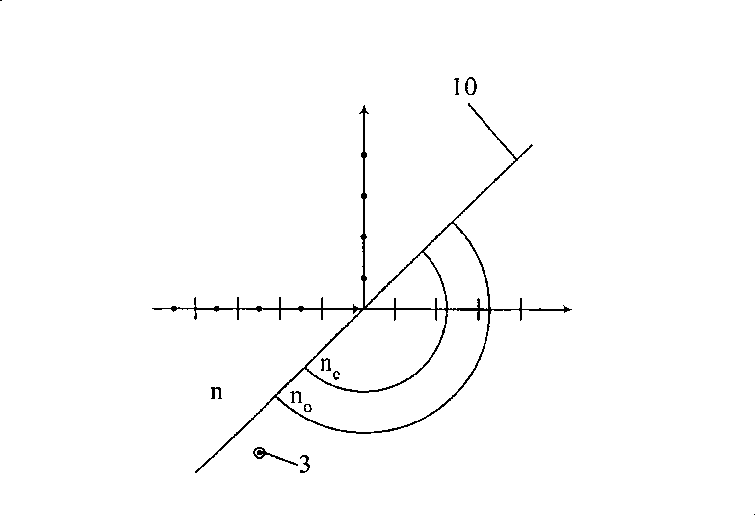
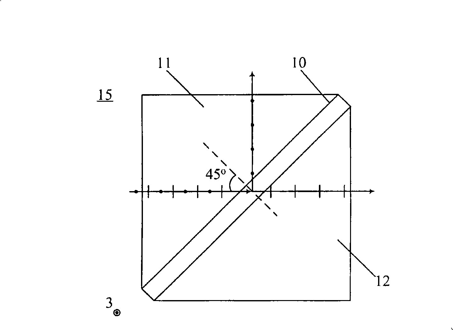
The invention discloses a polarization spectrometer which comprises at least one sub-wavelength grating and two optical prisms, and the sub-wavelength grating is clamped between the two optical prisms. The sub-wavelength grating can be equivalent to a uniaxial crystal and respectively has different refractive indexes for two linearly polarized lights (o light and e light) which are mutually orthogonal, thus leading the light in one of the polarization directions to satisfy the total reflection condition and be totally reflected out when a beam of light passes through the optical prisms and irradiates on the sub-wavelength grating by a certain angle; while the other light of the orthogonal polarization direction can just satisfy the refractive index matching and be totally transmitted out almost without loss, thus achieving the aim of separating the lights of two polarization directions. The invention also discloses a liquid crystal on silicon (LCoS) projection display device adopting the polarization spectrometer.

Description

technical field [0001] The present invention generally relates to a polarization beam splitting device, and in particular, relates to a polarization beam splitting device mainly used for projection display. The invention also relates to a projection display device using the polarization splitting device. Background technique [0002] Liquid crystal on silicon (LCoS) projection display is an important new display method. In particular, Chinese Patent Application Publication CN1570704A discloses a new display method, which uses two color LCoS devices to easily realize three-dimensional display and six primary color high-fidelity color display, and freely switch between these two display methods. This new display method is likely to be the mainstream of the future display direction. In this display system, a polarizing beamsplitter prism is used, which can project two mutually orthogonal linearly polarized lights onto two different LCoS devices respectively. However, the ext...

Claims


Application Information

Patent Timeline
Patent Type & Authority Applications(China)
IPC IPC(8): G02B27/28G02B5/30G02B5/04G03B21/00
Inventor 邵剑心樊斌
Owner JINGYING OPTICS
Learn More