
Steering column device

A technology of steering column and steering shaft, which is applied to the direction of steering column and steering control mounted on the vehicle, which can solve the problems of reducing the support rigidity of the steering column and delaying the timing of the start of the steering column, so as to achieve high support rigidity and stable impact The effect of energy absorption

Inactive Publication Date: 2008-10-22
NSK LTD
View PDF3 Cites 10 Cited by
  • Summary
  • Abstract
  • Description
  • Claims
  • Application Information

AI Technical Summary

Problems solved by technology

However, this will delay the start of the steering column during the secondary collision. On the other hand, in order to advance the start of the steering column during the secondary collision, it is enough to reduce the clamping force of the oblique pivot bolt, but the steering column will be reduced. Support rigidity

Method used


Image

  • Steering column device
  • Steering column device
  • Steering column device

Examples


Embodiment Construction

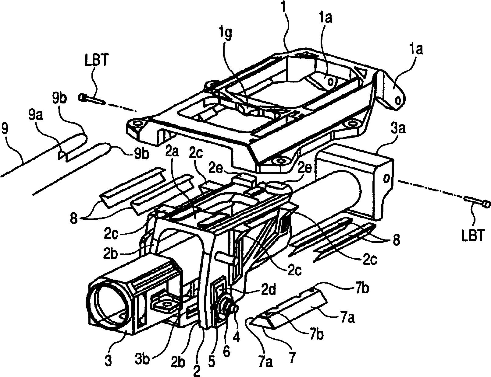
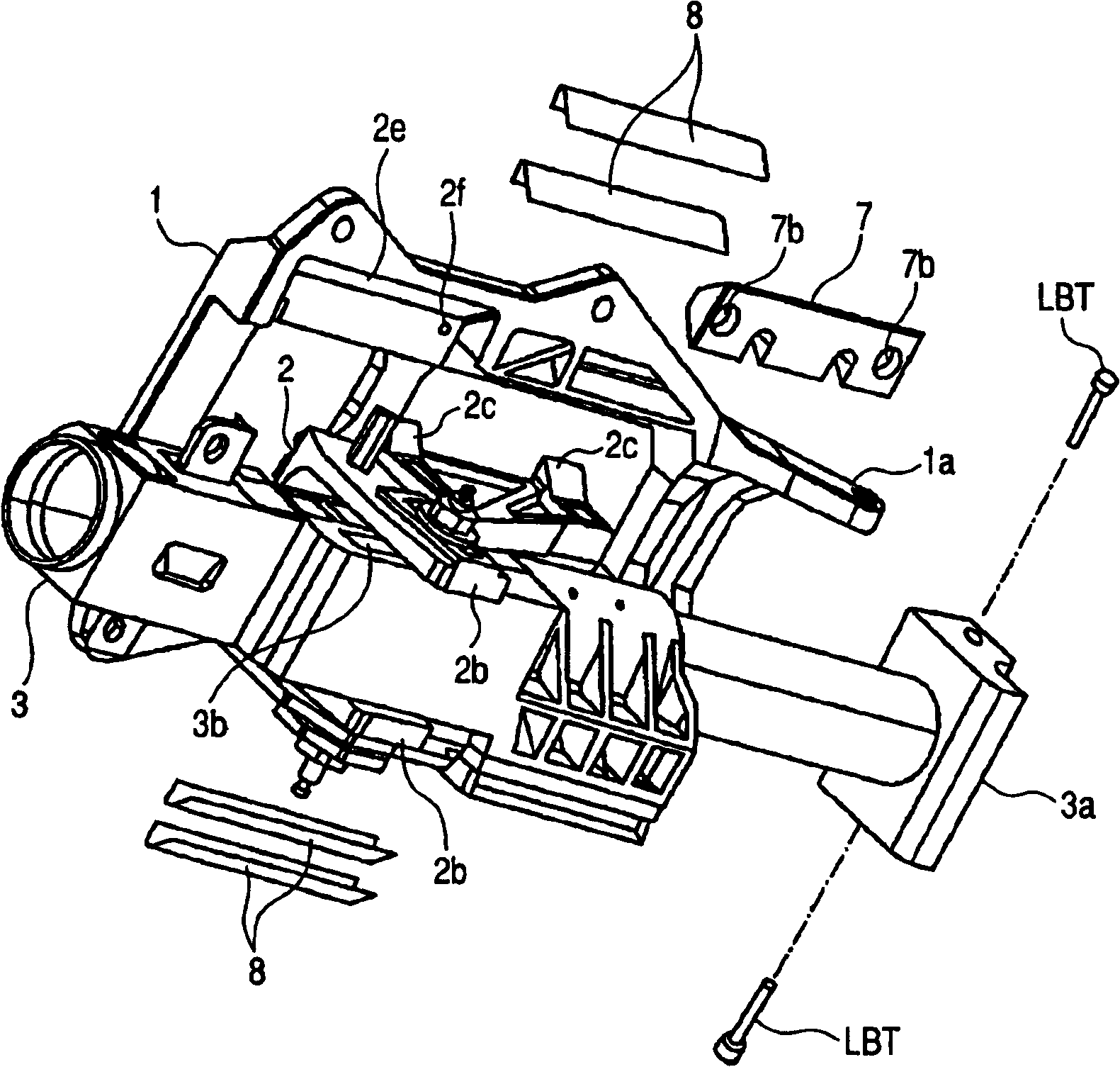
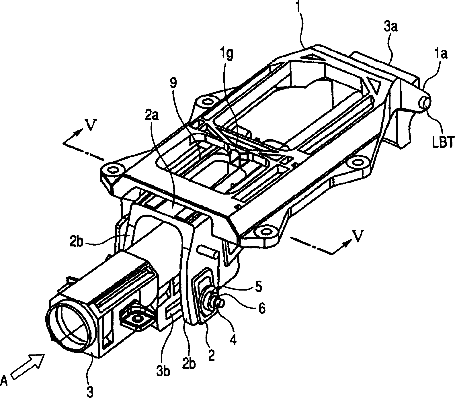
[0081] Hereinafter, a tilt / telescopic steering column device according to an embodiment of the present invention will be described with reference to the drawings. figure 1 It is an exploded perspective view of the steering column device according to this embodiment. figure 2 It is a perspective view of the steering column device according to the present embodiment viewed from below. image 3 It is a perspective view of the steering column device according to this embodiment in a normal state. Figure 4 It is a perspective view showing a state in which the steering column device according to this embodiment absorbs impact energy. Figure 5 To truncate with a plane containing V-V figure 2 The diagram of the structure viewed along the direction of the arrow.

[0082] fixed via the insert bracket FB (refer to Figure 5 , 7 ) The fixed bracket 1 of the vehicle body VB has a shape roughly in the shape of a "day" character, on the front side of the vehicle ( figure 1 (middle ...


PUM


Abstract

A steering column device in which a fixation member (7) is attached to a fixation bracket (1) by using bolts (BT, BT), which enables impact force at which a skid bracket (1) starts to slide to be set as desired by adjusting fastening force of the bolts (BT, BT).

Description

technical field [0001] The invention relates to a steering column device capable of absorbing the impact force of a secondary collision. In particular, it relates to a steering column device capable of providing comfortable operability to a driver and improving safety by providing a steering column with two opposing functions of high rigidity and reliable impact energy absorption. Background technique [0002] The steering column device is an important safety guarantee component of the vehicle. In particular, in order to ensure the safety of passengers, how to control the movement of the steering column device in the event of a vehicle collision is extremely important. Usually, the steering column device itself is equipped with an impact energy absorbing mechanism, and an airbag support member housed in the steering wheel also plays an important role. [0003] Currently, various concepts of impact energy absorbing mechanisms exist. Most of them focus on how to absorb the ...

Claims


Application Information

Patent Timeline
IPC IPC(8): B62D1/19B62D1/18
Inventor 柴崎弘山田康久
Owner NSK LTD
Learn More