Illumination system with optical concentrator and wavelength converting element

A technology of wavelength conversion components and optical concentrators, which is applied in the field of high radiance optical systems and can solve problems such as radiance loss

Inactive Publication Date: 2008-10-08
PHILIPS LUMILEDS LIGHTING CO LLC
View PDF15 Cites 24 Cited by
  • Summary
  • Abstract
  • Description
  • Claims
  • Application Information

AI Technical Summary

Problems solved by technology

This conversion usually results in a loss of emissivity, which renders such systems unacceptable for high brightness applications

Method used


Image

  • Illumination system with optical concentrator and wavelength converting element
  • Illumination system with optical concentrator and wavelength converting element
  • Illumination system with optical concentrator and wavelength converting element

Examples


Embodiment Construction

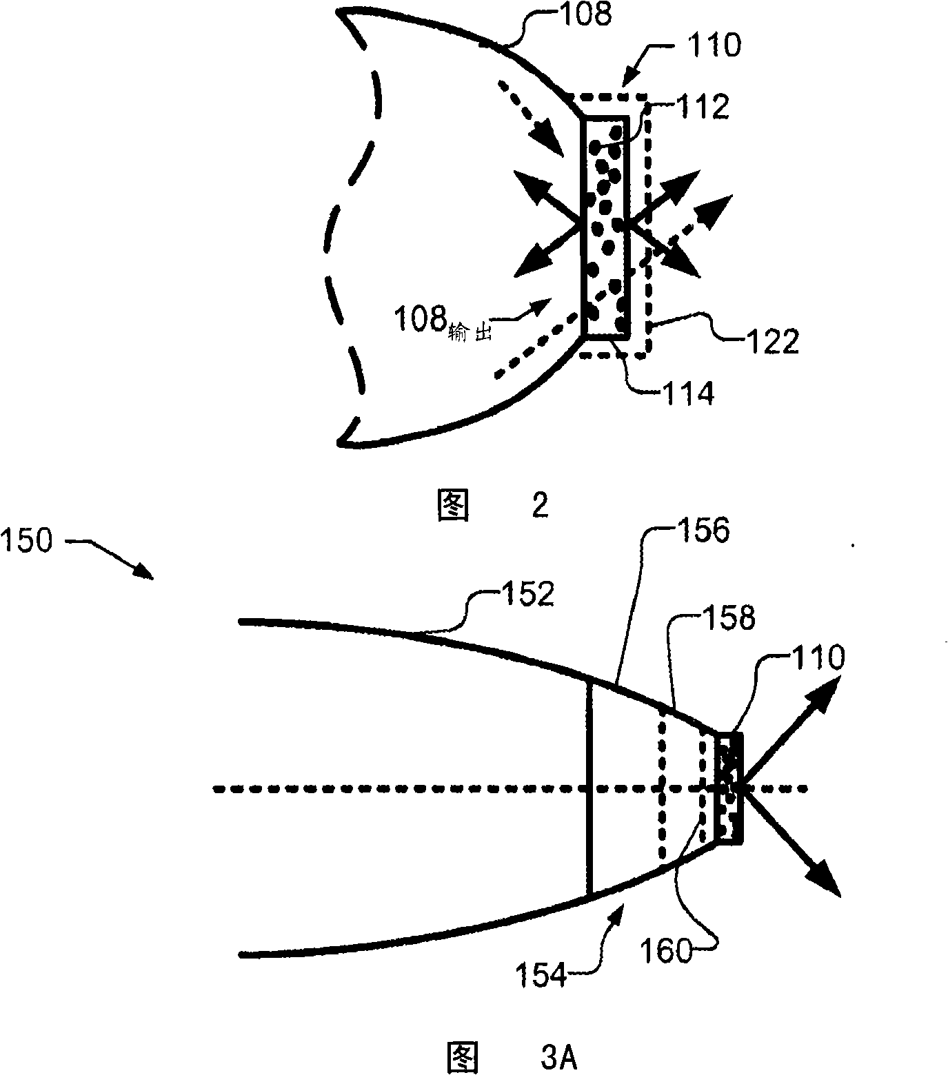
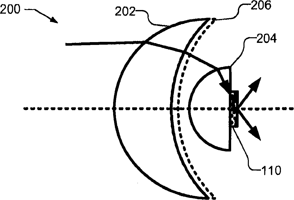
[0011] According to one embodiment of the present invention, the wavelength conversion element (such as a phosphor) is pumped through an optical concentrator with a high refractive index and the generated (converted) light is produced through a low refractive index medium (such as air) to improve Brightness or radiance of an optical system.

[0012] figure 1 An optical system 100 according to an embodiment of the invention is shown. Optical system 100 includes light emitting device 102, illustrated as a light emitting diode (LED) or an array of LEDs on a substrate, and collection optics 104. Collection optics 104 reduce the cone angle of the emission pattern from light emitting device 102 . For example, collection optics 104 can reduce a ±90° emission cone from light emitting device 102 to an emission pattern of ±30° angle. Collection optics 104 may be, for example, a right-angle converter, a compound parabolic concentrator (CPC), a condenser lens, a Fresnel lens, a lens us...


PUM


Abstract

A light emitting device includes a light emitting element, an optical concentrator, such as a compound parabolic concentrator, a dichroic filter between the light emitting element and the optical concentrator and a wavelength converting material, such as a phosphor. The optical concentrator receives light from the light emitting element, via the dichroic filter, and emits the light from an exit surface, which is smaller than the entrance surface. The optical concentrator may be manufactured from a material with a high refractive index, such as sapphire. The wavelength converting material is, e.g., disposed over the exit surface. The radiance of the wavelength converting material is increased by pumping the wavelength converting material through a high index of refraction material and outputting the converted light into a low refractive index medium, such as air.

Description

technical field [0001] The present invention relates generally to light emitting devices and in particular to high emissivity optical systems. Background technique [0002] Certain optical systems, such as projection systems and automotive headlights, require light sources with high emissivity, or brightness. Until recently, conventional light emitting diodes (LEDs) were not bright enough for these applications. However, even with current high-performance LEDs, it is difficult to meet the emissivity requirements of some optical systems. Furthermore, the brightness of LEDs is usually too low compared to high-intensity discharge lamps. This is especially true in systems that, for example, use phosphors to convert light emitted from LEDs to other wavelengths in order to produce white light. This conversion typically results in a loss of radiance, which renders such systems unacceptable for high brightness applications. [0003] Therefore, what is needed is an improved high ...

Claims


Application Information

Patent Timeline
IPC IPC(8): G02B17/06G02B17/08
CPCH04N9/3197H04N9/315
Inventor S·J·A·比尔休詹G·哈伯斯
Owner PHILIPS LUMILEDS LIGHTING CO LLC
Why Eureka
Try Eureka