Rotary compressor
A rotary compressor and eccentric rotation technology, which is applied in the direction of rotary piston machines, rotary piston pumps, rotary piston/oscillating piston pump components, etc., can solve problems such as wear, scorching, and staggering, and achieve reduction Effects of bearing load capacity, avoidance of fluid leakage, and improvement of reliability
- Summary
- Abstract
- Description
- Claims
- Application Information
AI Technical Summary
Problems solved by technology
Method used
Image
Examples
Embodiment 1
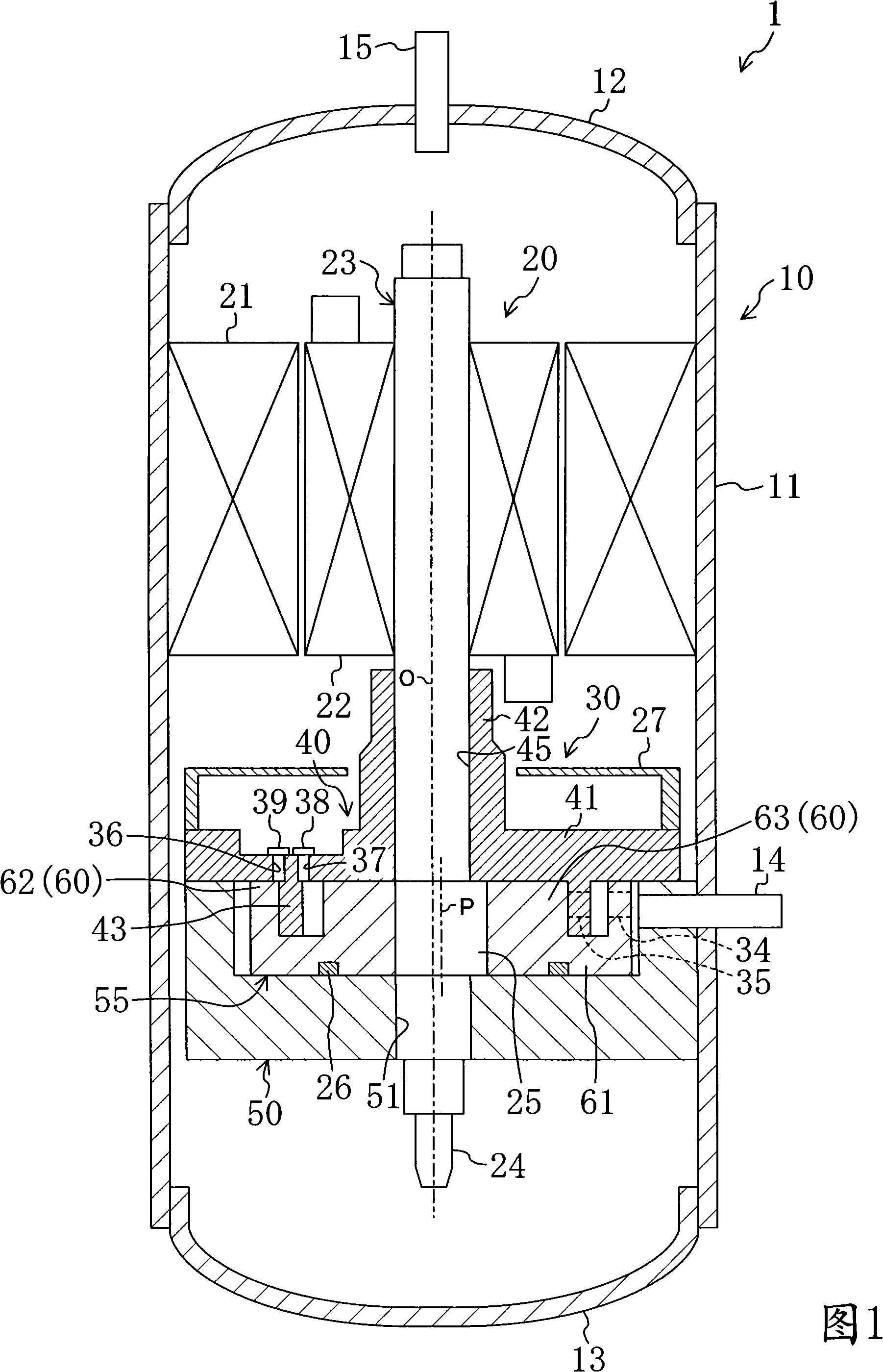
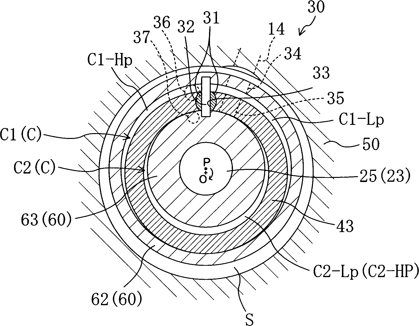
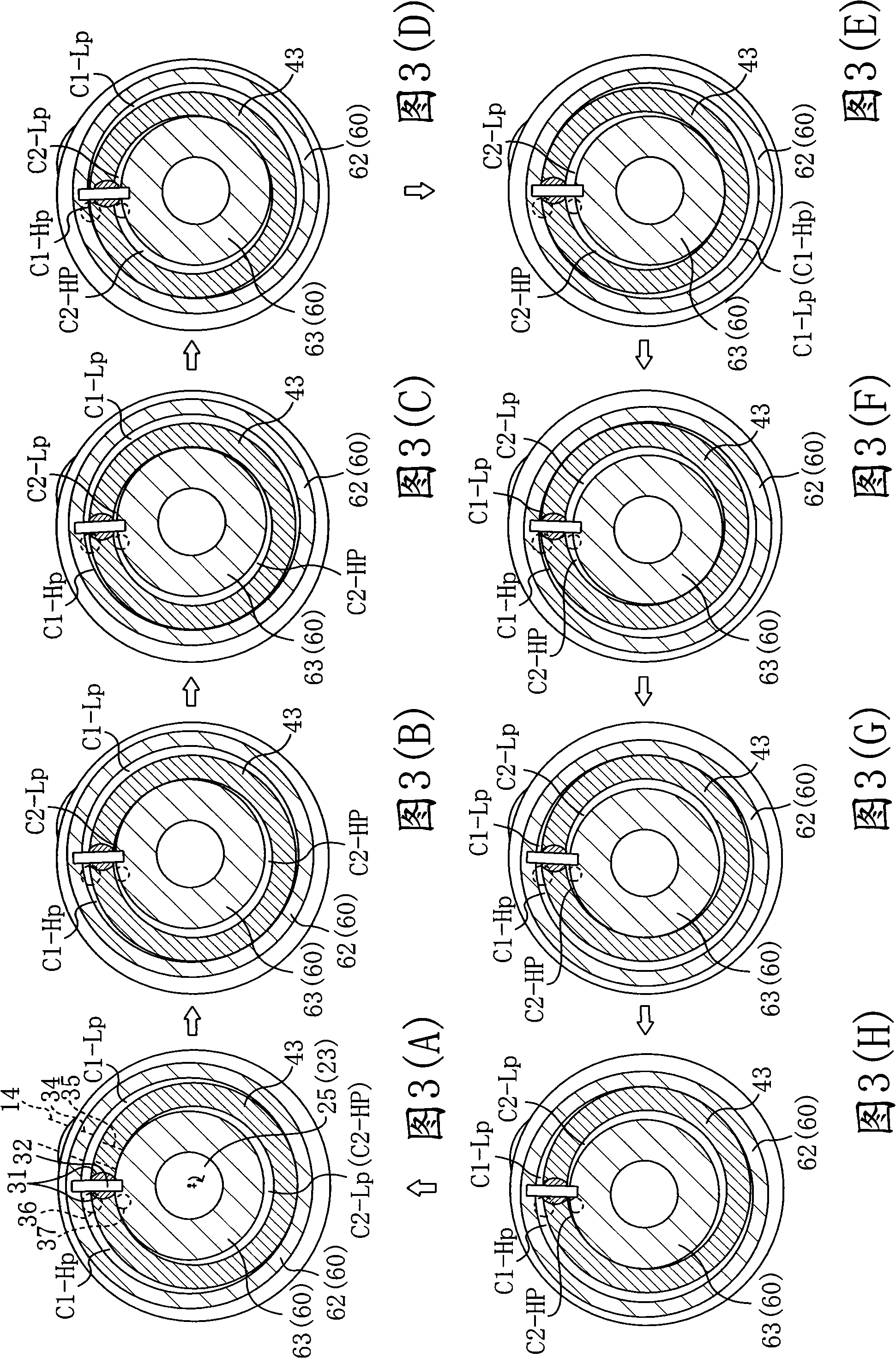
[0066] The rotary compressor of the first embodiment constitutes a so-called twin-cylinder compressor 1 in which refrigerant is compressed in two cylinder chambers formed on the same plane. The compressor 1 is used in a compression process for compressing refrigerant in a refrigerant cycle of a refrigerant circuit such as an air conditioner or a refrigeration device, for example.
[0067]
[0068] As shown in FIG. 1 , the compressor 1 includes a casing 10 , a motor 20 and a compression mechanism 30 .
[0069] The casing 10 constitutes a fully enclosed container with a long longitudinal length. The housing 10 includes a cylindrical housing 11 , an upper cover 12 fixed to the upper end of the housing 11 , and a lower cover 13 fixed to the lower end of the housing 11 . A suction pipe 14 penetrating through the housing 11 is provided on the lower side of the housing 11 . One end of the suction pipe 14 opens to the outside of the cabinet 10 , and the other end opens to the insi...
Embodiment 2
[0108] In the rotary compressor of the second embodiment, the configuration of the compression mechanism 30 is different from that of the compressor 1 of the first embodiment described above. Specifically, in the compression mechanism 30 of the above-mentioned first embodiment, the cylinder 60 on the movable side performs an eccentric rotational movement relative to the annular piston 43 on the fixed side, while in the compression mechanism 30 of the second embodiment, The annular piston 43 on the movable side performs eccentric rotational motion with respect to the cylinder 60 on the fixed side. Next, differences between the compressor 1 of the second embodiment and the first embodiment described above will be described.
[0109] As shown in FIG. 4 , the front head 40 is configured such that the first mirror plate 41 , the main bearing 45 and the cylinder 60 are integrally formed. The above-mentioned cylinder 60 is composed of a disc-shaped outer cylinder part 62 protruding ...
PUM
 Abstract
Description
Claims
Application Information
 - Generate Ideas
- Intellectual Property
- Life Sciences
- Materials
- Tech Scout
- Unparalleled Data Quality
- Higher Quality Content
- 60% Fewer Hallucinations
Browse by: Latest US Patents, China's latest patents, Technical Efficacy Thesaurus, Application Domain, Technology Topic, Popular Technical Reports.
© 2025 PatSnap. All rights reserved.Legal|Privacy policy|Modern Slavery Act Transparency Statement|Sitemap|About US| Contact US: help@patsnap.com


